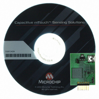
AC103003 Microchip Technology, AC103003 Datasheet

AC103003
Specifications of AC103003
Available stocks
Related parts for AC103003
AC103003 Summary of contents
Page 1
... Then, it discharges slowly through R1 until it reaches the trip point of the internal band gap reference of 0.6V. The output of the comparator will go high again and the cycle repeats itself. © 2008 Microchip Technology Inc. IMPLEMENTATION Capacitive sensing is implemented by turning the comparator into a relaxation oscillator. The output of ...
Page 2
... The detection scheme used to detect a finger press is based on the principle that there is rapid drop in frequency counts from the running average finger touches the pad, the capacitance increases and the frequency drops. To initialize the oscillator, the following sequence is needed: /4). The software then OSC © 2008 Microchip Technology Inc. ...
Page 3
... The upper trace shows the oscillator being turned on periodically for 100 ms. The lower trace shows the PIC microcontroller transmitting the real time data serially over the free available pin. © 2008 Microchip Technology Inc. AN1202 FIGURE 3: FREQUENCY BURSTS DETECTING A FINGER PRESS At this point the system is complete, except for the detection and signaling of a button press ...
Page 4
... Thus, the larger the pad, the greater the distance. Any material in between the hand and the sensor may influence the maximum distance. FIGURE 6: PROXIMITY SWITCH © 2008 Microchip Technology Inc ...
Page 5
... Reset until the operating parameters are met. Alternatively, a circuit shown in Figure 7 below can be used. This way, the MCLR pin can still be used as a general purpose input pin. © 2008 Microchip Technology Inc. FIGURE 7: CIRCUIT BOARD DESCRIPTION The full schematic is illustrated in Appendix A. The board can be powered by an external power supply or by the serial port ...
Page 6
... Additional reference materials include: AN1101, “Introduction to Capacitive Sensing” AN1102, “Layout for Capacitive Sensing” AN1103, “Software Handling for Capacitive Sensing” AN1104, “Capacitive Mini-Button Configurations” DS01202B-page 6 © 2008 Microchip Technology Inc. ...
Page 7
... Appendix A. Full Circuit Schematic © 2008 Microchip Technology Inc. CAPACITIVE SENSING WITH PIC10F DS01202B-page 7 ...
Page 8
... Capacitive Sensing with PIC10F NOTES: DS01202B-page 8 © 2008 Microchip Technology Inc. ...
Page 9
... PowerMate, PowerTool, REAL ICE, rfLAB, Select Mode, Total Endurance, WiperLock and ZENA are trademarks of Microchip Technology Incorporated in the U.S.A. and other countries. SQTP is a service mark of Microchip Technology Incorporated in the U.S.A. All other trademarks mentioned herein are property of their respective companies. ...
Page 10
... Fax: 886-3-572-6459 Taiwan - Kaohsiung Tel: 886-7-536-4818 Fax: 886-7-536-4803 Taiwan - Taipei Tel: 886-2-2500-6610 Fax: 886-2-2508-0102 Thailand - Bangkok Tel: 66-2-694-1351 Fax: 66-2-694-1350 © 2008 Microchip Technology Inc. EUROPE Austria - Wels Tel: 43-7242-2244-39 Fax: 43-7242-2244-393 Denmark - Copenhagen Tel: 45-4450-2828 Fax: 45-4485-2829 France - Paris Tel: 33-1-69-53-63-20 ...


