FHS 40-P KIT 9-1P LEM USA Inc, FHS 40-P KIT 9-1P Datasheet

FHS 40 PCB KIT 30/78A

FHS 40-P KIT 9-1P

Manufacturer Part Number
FHS 40-P KIT 9-1P
Description
FHS 40 PCB KIT 30/78A
Manufacturer
LEM USA Inc

Specifications of FHS 40-P KIT 9-1P

Sensor Type
Current Sensor
Sensing Range
±78A
Interface
Analog
Sensitivity
25.8 mV/A
Voltage - Supply
4.75 V ~ 5.25 V
Embedded
No
Utilized Ic / Part
FHS 40
Lead Free Status / RoHS Status
Lead free / RoHS Compliant
Other names
398-1069
User guide for FHS 40-P
Current Transducer
FHS 40-P Kit 9 (G2.00.23.108.0)
Evaluation PCB
Connectors Pin-OUT
The board has two single row connectors J1 and J2.
Manufacturer and reference for J1, J2: PRECI-DIP, 310-13-120-41-001001.
Thermal Capability
The enclosed evaluation PCB has tracks with thickness of 70 µm.
The dimensions of the tracks drawn on the evaluation PCB lead to some limitations on the maximum continuous
current which can go through the PCB track.
Remark: under normal operating conditions, temperature of some parts of this product might exceed 70°C.
070206/0 KIT N°9
It has the following pin-out:
The four pin one (J1) makes possible to supply the board and access to the output voltage easily.
The two pin one (J2) makes possible to access to the fast output voltage and standby input easily.
Pin #
Pin #
1
2
3
4
1
2
V
Standby Standby, Set operating or Standby modes (see datasheet for connection)
Name
Name
OUTFAST
V
V
V
OUT
REF
0
C
Reference voltage input/output
Output voltage is proportional to the current in the PCB track,
V
Note that the output voltage is positive when the current flows inside the
tracks according to the direction marked “I
0 V
Positive supply voltage 4.75-5.25V; typical consumption 15 mA
V
(see datasheet for connection)
OUT
OUTFAST
= V
, fast output signal; note that this output is opposite to V
REF
+ G
I
*I
P
Description J1 connector
Description J2 connector
P
” on the PCB
OUT
Page 1/5

Related parts for FHS 40-P KIT 9-1P

FHS 40-P KIT 9-1P Summary of contents

Page 1

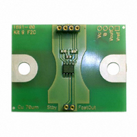
... User guide for FHS 40-P Current Transducer FHS 40-P Kit 9 (G2.00.23.108.0) Evaluation PCB Connectors Pin-OUT The board has two single row connectors J1 and J2. • The four pin one (J1) makes possible to supply the board and access to the output voltage easily. It has the following pin-out: ...

Page 2

Primary track dimensions [mm Thermal simulation Cu 70 µm: Track thickness 70 µm, PCB thickness 1.6 mm, T 070206/0 KIT N°9 = 81°C, natural convection rms Page ...

Page 3

The following figures should be taken into account to avoid overheating: (T primary track = 115 °C) Maxi rms current I [ 10.0 20.0 30.0 40.0 50.0 Typical primary current for a maximum track temperature of 115°C (natural ...

Page 4

Connect then the primary between pins I Features Magnetic field sensitivity Current sensitivity Measuring range Frequency range Isolation characteristics Rms voltage for AC isolation test, 50-60 Hz, 1 min Impulse withstand voltage 1.2/50 µs Creepage/Clearance distance Comparative ...

Page 5

Application example According to EN 50178 and IEC 61010-1 standards and following conditions: • Rated isolation voltage 300 V (IEC 61010-1) • Reinforced isolation • Over voltage category OV III • Pollution degree PD1 • Non-uniform field Safety This transducer ...

Related keywords