STEVAL-ICB004V1 STMicroelectronics, STEVAL-ICB004V1 Datasheet
STEVAL-ICB004V1
Specifications of STEVAL-ICB004V1


Related parts for STEVAL-ICB004V1


STEVAL-ICB004V1 Summary of contents
Page 1
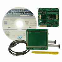
... Advanced resistive touchscreen controller demonstration kit Introduction This document describes the functioning of the touchscreen controller demonstration board included in the STEVAL-ICB004V1 demonstration kit. The system is designed to demonstrate the high performance resistive touch sensing capabilities of the STMPE811 touchscreen controller. This board is also compatible with STMPE610, refer to Figure 1 ...
Page 2
... Contents Contents 1 STEVAL-ICB004V1 demonstration kit description . . . . . . . . . . . . . . . . . 6 2 Getting started . . . . . . . . . . . . . . . . . . . . . . . . . . . . . . . . . . . . . . . . . . . . . . 7 2.1 Package contents . . . . . . . . . . . . . . . . . . . . . . . . . . . . . . . . . . . . . . . . . . . . 7 2.2 Hardware installation . . . . . . . . . . . . . . . . . . . . . . . . . . . . . . . . . . . . . . . . . 7 2.3 Software installation . . . . . . . . . . . . . . . . . . . . . . . . . . . . . . . . . . . . . . . . . . 7 2.3.1 2.3.2 2.3.3 3 Hardware layout . . . . . . . . . . . . . . . . . . . . . . . . . . . . . . . . . . . . . . . . . . . . . 9 4 Hardware details . . . . . . . . . . . . . . . . . . . . . . . . . . . . . . . . . . . . . . . . . . . 10 4.1 Power control 4.2 Clocking 4.3 Reset control . . . . . . . . . . . . . . . . . . . . . . . . . . . . . . . . . . . . . . . . . . . . . . 10 4.4 Debug JTAG interface 4.5 2-pin jumper headers J11, J12, ADC1 . . . . . . . . . . . . . . . . . . . . . . . . . . . 10 4 ...
Page 3
UM0772 5.3 DfuSe demonstration . . . . . . . . . . . . . . . . . . . . . . . . . . . . . . . . . . . . ...
Page 4
List of tables List of tables Table 1. Board LED indications . . . . . . . . . . . . . . . . . . . . . . . . . . . . . ...
Page 5
UM0772 List of figures Figure 1. Advanced resistive touchscreen controller demonstration kit . . . . . . . . . . . . . . . . . . . . . . . . 1 Figure 2. Advanced ...
Page 6
... The board offers the added functionality of a USB universal dongle for I interfaces, and DFU (device firmware upgrade) protocol for run-time firmware upgrades. Multi-functionality in a single board renders the STEVAL-ICB004V1 a multi-purpose kit. The system is designed to offer users a product evaluation platform for the touchscreen controller STMPE811 ...
Page 7
... UM0772 2 Getting started 2.1 Package contents The demonstration kit includes the following items: ● Hardware: – STEVAL-ICB004V1 demonstration board – USB A to mini-B cable – Stylus pen – IDC cable for 10-pin IDC connectors ● Software: – S-Touch™ resistive touchscreen controller demonstration (STPME811) – ...
Page 8
... After package installation, connect the board. – On board connection, the PC prompts for driver installation. – Browse to the driver available at path: C:\Program Files \STMicroelectronics\ S- Touch resistive touchscreen Demo\Driver – The S-Touch™ resistive touchscreen controller demo GUI installation is complete. Open the application GUI of interest and run the demo. ...
Page 9
UM0772 3 Hardware layout The demonstration kit hardware is designed using a sectional approach to offer multiple functionalities to users. Figure 3. Hardware layout: top view Figure 4. Hardware layout: bottom view Doc ID 16158 Rev 3 Hardware layout 9/33 ...
Page 10
Hardware details 4 Hardware details 4.1 Power control J5 The demonstration board can be powered from the USB connector J5. All other required voltages are provided by the on-board voltage regulator. 4.2 Clocking Y1 The clock source available on the ...
Page 11
UM0772 These jumper headers are available to the user to manage the connection/disconnection of the touchscreen controller to/from the microcontroller on run-time. Table 3. 3-pin jumper headers Jumper Close: 1-2 2 STM32 I C clock line is connected to J6 ...
Page 12
... STMPE610, pin number and pin number 9 has limited functionality compared to the STMPE811. Therefore, if the STMPE610 is used in the STEVAL-ICB004V1, switch SW1 (pin 8 of The STMPE811) does not function. However, touch sensing and all remaining GPIOs are fully functional on the board with the STMPE610 ...
Page 13
UM0772 4.13 Voltage regulators U3, U4 ● U3: LD1117D33TR (low drop fixed positive voltage, 3.3 V regulator) is used to convert the USB VDD 3.3 V. ● U4: L6935 (ultra low drop output linear regulator ...
Page 14
Running the demonstration 5 Running the demonstration 5.1 S-Touch™ resistive touchscreen controller demonstration (STPME811) The following represents the default demonstration configuration of the demonstration kit. Demo application: ● The S-Touch™ resistive touchscreen controller demonstration (STPME811) maps the stylus movement on ...
Page 15
UM0772 – Moving average size – Direction choice: XY/XYZ – Axis distance filters How it works: ● Perform the PC GUI installation as described in the software installation section ● Ensure that J6, J7, J8 and J9 are connected with ...
Page 16
Running the demonstration Figure 6. Universal dongle GUI ● Users can check whether or not the board is connected by clicking the connection check button. If the board is not connected, then the user sees the following message Figure 7. ...
Page 17
UM0772 2 Using I C interface: ● To connect the I ● Once the synchronous interface is selected, an additional menu for the synchronous interface allows selection between I Figure 9. Selection of I ● Selection of the I in ...
Page 18
Running the demonstration Figure 11. J3 interpretation for I 2 ● GPIO settings: – GPIOs may be required for sensor slave interfacing to the host, along with I protocol line connections. The GPIO pins may act as control ...
Page 19
UM0772 Figure 13. GPIO setting window – By selecting the option in the GPIO setting window, one can set the GPIO to different modes, such as simple input mode, input with interrupt and push-pull output mode – GPIO ...
Page 20
Running the demonstration Figure 16. GPIO1 setting in push-pull output mode Note: For this kit, GPIO with PWM mode is not supported. 2 ● header settings – Once the GPIO settings are complete, the daughter board can be ...
Page 21
UM0772 2 Figure 18 read/write window – Here, depending on the slave device, the register address length can be selected (from bytes, 0 byte length is used for random read and write operations) – After ...
Page 22
Running the demonstration Figure 19. SPI interface window – At this point, the PC GUI is ready to be used for testing SPI-based slave devices. However, before it can be used the connection to jumper J3, as shown in Figure ...
Page 23
UM0772 Figure 21. SPI pin interface in PC GUI – Follow the instructions in the I settings. Note: In this case, only GPIO1 and GPIO2 are unavailable in the default hardware configuration. R3 and R5 should be de-soldered if using ...
Page 24
Running the demonstration Figure 23. SPI read/write window – So depending on the slave device, the user can select the register address length (from bytes; 0 byte length is used for random read and write operations). After ...
Page 25
... To work in DFU mode, connect jumper J11 ● Open the DfuSe GUI and perform the firmware upgrade as per requirements Note: For more details regarding DfuSe operation, refer to user manual UM0412 available at C:\Program Files\STMicroelectronics\DfuSe\Sources\Doc after DfuSe GUI installation. Doc ID 16158 Rev 3 Running the demonstration 25/33 ...
Page 26
Schematic diagrams for the touchscreen controller demonstration board 6 Schematic diagrams for the touchscreen controller demonstration board Figure 24. Circuit schematics 26/33 Doc ID 16158 Rev 3 UM0772 ...
Page 27
... Quartz crystal 8 MHz oscillator Manufacturer’s order Package Manufacturer code / orderable part number QFN16 STMicroelectronics STMPE811QTR VFQFPN36 STMicroelectronics STM32F103T8U6 SO-8 STMicroelectronics LD1117D33TR VFQFPN20 STMicroelectronics L6935 SOT23-3 (WX) STMicroelectronics STM1001SWX6F SOT-666 STMicroelectronics ESDAULC6-3BP6 SMD ECS Inc ECS-80-S-5PX-TR Supplier order Supplier code or equivalent Digi-Key XC1243CT-ND ...
Page 28
Table 7. BOM (continued) Component Category Ref. des. description Box header, surface mount, 20-way, 2x10 J2 pin, 2. 2.54 mm pitch box header, surface mount, 10-way, 2x5 J3,J4 Connectors pin, 2. 2.54 and jumpers mm pitch ...
Page 29
Table 7. BOM (continued) Component Category Ref. des. description C1,C2,C3, C5, C6,C8,C11,C12, C13,C14,C15, C16,C17,C19, 100 nF C21,C22,C24, C26,C27,C28, C32 1 µF/25 V C33 tantalum SMD Capacitors 10 µF/25 V C9,C10,C18,C23 tantalum SMD 22 µF/25 V C20 ...
Page 30
Table 7. BOM (continued) Component Category Ref. des. description R1 15 kΩ 470 Ω R2,R27,R31 R3,R5 4.7 kΩ R4,R11,R16,R19, R23,R24 R6,R7,R9,R10, R12,R13,R14, R15,R17,R18, 10 kΩ Resistors R21,R25,R26, R28,R29 R8,R34 1 MΩ 500 Ω R20 R22 50 kΩ R30 1.5 kΩ ...
Page 31
Table 7. BOM (continued) Component Category Ref. des. description Push button switch, SW1, SW2 SMD 4-wire resistive Touchscreen touchscreen USB cable: USB A to USB mini B cable mini-B connector Adhesive touchscreen Misc Command strips mounting strips components Touchscreen Resistive ...
Page 32
Revision history 8 Revision history Table 8. Document revision history Date 19-Feb-2010 10-Mar-2010 26-Apr-2010 32/33 Revision 1 Initial release. 2 Figure 1 and 2 merged in 3 Modified: Section 4.11: Touchscreen controller U1 Doc ID 16158 Rev 3 Changes Figure ...
Page 33
... UM0772 Information in this document is provided solely in connection with ST products. STMicroelectronics NV and its subsidiaries (“ST”) reserve the right to make changes, corrections, modifications or improvements, to this document, and the products and services described herein at any time, without notice. All ST products are sold pursuant to ST’s terms and conditions of sale. ...