STEVAL-IFS012V1 STMicroelectronics, STEVAL-IFS012V1 Datasheet - Page 107
STEVAL-IFS012V1
Manufacturer Part Number
STEVAL-IFS012V1
Description
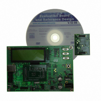
BOARD ST72651AR6/STTS75/STLM20
Manufacturer
STMicroelectronics
Specifications of STEVAL-IFS012V1
Sensor Type
Temperature
Sensing Range
Depends on IC
Interface
I²C, USB
Sensitivity
Depends on IC
Voltage - Supply
5V
Embedded
Yes, MCU, 8-Bit
Utilized Ic / Part
ST72F651AR6, STTS75, STLM20
Lead Free Status / RoHS Status
Lead free / RoHS Compliant
Other names
497-8419
Available stocks
Company
Part Number
Manufacturer
Quantity
Price


I²C SINGLE MASTER BUS INTERFACE (Cont’d)
11.7.4 Functional Description (Master Mode)
Refer to the CR, SR1 and SR2 registers in
11.7.7. for the bit definitions.
By default the I
(M/IDL bit is cleared) except when it initiates a
transmit or receive sequence.
To switch from default idle mode to Master mode a
Start condition generation is needed.
Start condition and Transmit Slave address
Setting the START bit causes the interface to
switch to Master mode (M/IDL bit set) and genera-
tes a Start condition.
Once the Start condition is sent:
– The EVF and SB bits are set by hardware with
Then the master waits for a read of the SR1 regis-
ter followed by a write in the DR register with the
Slave address byte, holding the SCL line low
(see
Then the slave address byte is sent to the SDA
line via the internal shift register.
After completion of this transfer (and acknowledge
from the slave if the ACK bit is set):
– The EVF bit is set by hardware with interrupt
Then the master waits for a read of the SR1 regis-
ter followed by a write in the CR register (for exam-
ple set PE bit), holding the SCL line low (see
gure 64
Next the master must enter Receiver or Transmit-
ter mode.
Master Receiver
Following the address transmission and after SR1
and CR registers have been accessed, the master
receives bytes from the SDA line into the DR regis-
ter via the internal shift register. After each byte
the interface generates in sequence:
– Acknowledge pulse if if the ACK bit is set
– EVF and BTF bits are set by hardware with an in-
Then the interface waits for a read of the SR1 re-
gister followed by a read of the DR register, hol-
an interrupt if the ITE bit is set.
generation if the ITE bit is set.
terrupt if the ITE bit is set.
Figure 64
Transfer sequencing EV2).
Transfer sequencing EV1).
2
C interface operates in idle mode
Section
Doc ID 7215 Rev 4
Fi-
ding the SCL line low (see
quencing EV3).
To close the communication: before reading the
last byte from the DR register, set the STOP bit to
generate the Stop condition. The interface goes
automatically back to idle mode (M/IDL bit clea-
red).
Note: In order to generate the non-acknowledge
pulse after the last received data byte, the ACK bit
must be cleared just before reading the second
last data byte.
Master Transmitter
Following the address transmission and after SR1
register has been read, the master sends bytes
from the DR register to the SDA line via the inter-
nal shift register.
The master waits for a read of the SR1 register fol-
lowed by a write in the DR register, holding the
SCL line low (see
EV4).
When the acknowledge bit is received, the
interface sets:
– EVF and BTF bits with an interrupt if the ITE bit
To close the communication: after writing the last
byte to the DR register, set the STOP bit to gene-
rate the Stop condition. The interface goes auto-
matically back to idle mode (M/IDL bit cleared).
Error Case
– AF: Detection of a non-acknowledge bit. In this
Note: In the event of this error, the SCL line is not
held low, however, the SDA line can remain low if
the last bits transmitted are all 0. While AF=1, the
SCL line may be held low due to SB or BTF flags
that are set at the same time. It is then necessary
to release both lines by software.
is set.
case, the EVF and AF bits are set by hardware
with an interrupt if the ITE bit is set. To resume,
set the START or STOP bit. The AF bit is cleared
by reading the I2CSR2 register. However, if read
before the completion of the transmission, the AF
flag will be set again, thus possibly generating a
new interrupt. Software must ensure either that
the SCL line is back at 0 before reading the SR2
register, or be able to correctly handle a second
interrupt during the 9th pulse of a transmitted
byte.
Figure 64
Figure 64
Transfer sequencing
ST72651AR6
Transfer se-
107/161
Related parts for STEVAL-IFS012V1
Image
Part Number
Description
Manufacturer
Datasheet
Request
R

Part Number:
Description:
BOARD EVAL SPZB260 MOD FOR STR9
Manufacturer:
STMicroelectronics
Datasheet:

Part Number:
Description:
BOARD EVAL EXTENSION SN250
Manufacturer:
STMicroelectronics
Datasheet:

Part Number:
Description:
BOARD EVAL AB-54003L-512
Manufacturer:
STMicroelectronics
Datasheet:

Part Number:
Description:
BOARD REF DESIGN RF DMOS PWR AMP
Manufacturer:
STMicroelectronics
Datasheet:

Part Number:
Description:
BOARD EVAL PWR AMP AB-84008L-470
Manufacturer:
STMicroelectronics
Datasheet:

Part Number:
Description:
BOARD EVAL FOR STM32F103XX
Manufacturer:
STMicroelectronics
Datasheet:

Part Number:
Description:
BOARD EVAL AB-54003L-512
Manufacturer:
STMicroelectronics
Datasheet:

Part Number:
Description:
BOARD SMART PLUG STM32 SPZB260PR
Manufacturer:
STMicroelectronics
Datasheet:

Part Number:
Description:
BOARD DEMO BLUETOOTH SPBT2532C2
Manufacturer:
STMicroelectronics
Datasheet:
Part Number:
Description:
ZIGBEE USB DONGLE EVAL KIT
Manufacturer:
STMicroelectronics
Datasheet:
Part Number:
Description:
STMicroelectronics [RIPPLE-CARRY BINARY COUNTER/DIVIDERS]
Manufacturer:
STMicroelectronics
Datasheet:
Part Number:
Description:
STMicroelectronics [LIQUID-CRYSTAL DISPLAY DRIVERS]
Manufacturer:
STMicroelectronics
Datasheet:

Part Number:
Description:
BOARD EVAL FOR MEMS SENSORS
Manufacturer:
STMicroelectronics
Datasheet: