DM300024 Microchip Technology, DM300024 Datasheet
DM300024
Specifications of DM300024
Available stocks


Related parts for DM300024

DM300024 Summary of contents
Page 1
... Microchip Technology Inc. dsPICDEM™ 1.1 Plus Development Board User’s Guide DS70099D ...
Page 2
... Select Mode, Smart Serial, SmartTel, Total Endurance, UNI/O, WiperLock and ZENA are trademarks of Microchip Technology Incorporated in the U.S.A. and other countries. SQTP is a service mark of Microchip Technology Incorporated in the U.S.A. All other trademarks mentioned herein are property of their respective companies. ...
Page 3
... Programming the Chip ................................................................................. 51 4.7 Debugging the Code .................................................................................... 55 4.8 Additional Code Examples ........................................................................... 59 Chapter 5. dsPICDEM™ 1.1 Development Hardware 5.1 dsPICDEM™ 1.1 Plus Development Board Hardware Overview ................. 61 © 2006 Microchip Technology Inc. dsPICDEM™ 1.1 PLUS DEVELOPMENT BOARD Table of Contents USER’S GUIDE ...
Page 4
... A.1 Introduction .................................................................................................. 67 A.2 Highlights ..................................................................................................... 67 Appendix B. LCD Controller Specification B.1 Overview ...................................................................................................... 75 B.2 LCD Controller Interface .............................................................................. 75 B.3 Commands ................................................................................................... 76 B.4 General Commands ..................................................................................... 78 B.5 Character commands ................................................................................... 79 B.6 Pixel commands ........................................................................................... 81 B.7 Column commands ...................................................................................... 82 B.8 Examples ..................................................................................................... 83 Index .............................................................................................................................85 Worldwide Sales and Service .....................................................................................88 DS70099D-page iv © 2006 Microchip Technology Inc. ...
Page 5
... MPLAB devices. • Chapter 3: Demonstration Program Operation – This chapter presents a detailed description of the operational functionality of the sample code, which is preprogrammed into the dsPIC30F device. © 2006 Microchip Technology Inc. dsPICDEM™ 1.1 PLUS DEVELOPMENT BOARD Preface NOTICE TO CUSTOMERS ® ...
Page 6
... Index – This section provides cross-reference listing of terms, features and sections of this document. • Worldwide Sales and Service – A listing of Microchip sales and service locations and telephone numbers worldwide. DS70099D-page 2 ® ICD 2 using dsPIC30F devices. © 2006 Microchip Technology Inc. ...
Page 7
... N‘Rnnnn Text in angle brackets < > Courier New font: Plain Courier New Italic Courier New Square brackets [ ] Curly brackets and pipe character Ellipses... © 2006 Microchip Technology Inc. Represents Referenced books MPLAB Emphasized text ...is the only compiler... A window the Output window A dialog ...
Page 8
... MPLAB ASM30, MPLAB This document details Microchip Technology’s language tools for dsPIC DSC devices based on GNU technology. The language tools discussed are: • MPLAB ASM30 Assembler • MPLAB LINK30 Linker • MPLAB LIB30 Archiver/Librarian • ...
Page 9
... Consult this document for more information pertaining to the installation and features of the MPLAB Integrated Development Environment (IDE) Software. To obtain any of these documents, contact the nearest Microchip sales location (see back page) or visit the Microchip web site at: www.microchip.com. © 2006 Microchip Technology Inc. Preface DS70099D-page 5 ...
Page 10
... Programmers – The latest information on Microchip programmers. These include the MPLAB PM3 and PRO MATE Plus and PICkit DS70099D-page 6 ® II device programmers and the PICSTART ™ 1 development programmers. ® ® © 2006 Microchip Technology Inc. ...
Page 11
... Added tutorial and code examples for using the dsPICDEM™ 1.1 Plus Develop- ment Board with dsPIC33F and PIC24H/F devices (see Chapter 4. “Using dsPIC33F and PIC24H/24F Devices”). Revision C (September 2005) • Last Release of this Document. • Previous releases contained Advance Information that was updated in Revision C. © 2006 Microchip Technology Inc. Preface DS70099D-page 7 ...
Page 12
... Plus Development Board User’s Guide NOTES: DS70099D-page 8 © 2006 Microchip Technology Inc. ...
Page 13
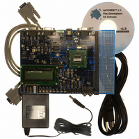
... RS-232 Interface Cable • dsPICDEM™ 1.1 Plus Development Board Kit CD containing demonstration programs FIGURE 1- © 2006 Microchip Technology Inc. dsPICDEM™ 1.1 PLUS DEVELOPMENT BOARD ® microcontrollers. ds PICDEM™ 1.1 Demonstration Program dsPICDEM™ 1.1 PLUS DEVELOPMENT BOARD 7 10 ...
Page 14
... Two RS-232 communication channels • 6-pin terminal block and configuration jumper for RS-485 and RS-422 communication on UART1 from the dsPIC DSC device • Single CAN communication channel DS70099D-page 10 dsPIC30F6014A PLUG-IN MODULE DD and AV with direct input DD © 2006 Microchip Technology Inc. ...
Page 15
... Prototype area for user hardware 1.5 SUPPORTED PLUG-IN MODULES The dsPICDEM™ 1.1 Plus Development Board supports these Plug-In Modules: • dsPIC30F6014A 80L Plug-In Module (MA300014) • dsPIC33FJ256GP710 100-to-80L Plug-In Module (MA330012) © 2006 Microchip Technology Inc. Introduction DS70099D-page 11 ...
Page 16
... Dual Tone Multi-Frequency (DTMF) Generation Switches SW2-SW4 select one of these three choices. Each choice offers a submenu, which provides for additional options using switches SW1-SW4. Refer to Chapter 3. “dsPIC30F Demonstration Program Operation” for full details on the demonstration code operation. DS70099D-page 12 © 2006 Microchip Technology Inc. ...
Page 17
... There are four steps to this tutorial: 1. Create a project in MPLAB IDE. 2. Assemble and link the code. 3. Program the chip with the MPLAB ICD 2. 4. Debug the code with the MPLAB ICD 2. © 2006 Microchip Technology Inc. dsPICDEM™ 1.1 PLUS DEVELOPMENT BOARD USER’S GUIDE DS70099D-page 13 ...
Page 18
... Close any workspace that might be open (File>Close Workspace). 3. From the Project menu, select Project Wizard. 4. From the Welcome screen, click Next> to display the Project Wizard Step One dialog (see Figure 2-1). FIGURE 2-1: DS70099D-page 14 PROJECT WIZARD, STEP 1, SELECT A DEVICE © 2006 Microchip Technology Inc. ...
Page 19
... Click Next> to continue. The Project Wizard Step Three dialog displays (see Figure 2-3). Note: The tool locations for your environment may be different from those shown in this tutorial. © 2006 Microchip Technology Inc. Using dsPIC30F Devices PROJECT WIZARD, STEP 2, SELECT LANGUAGE TOOLSUITE DS70099D-page 15 ...
Page 20
... In the Project Name text box, type MyProject. 2. Click Browse... and navigate to C:\Tutorial to place your project in the Tutorial folder. 3. Click Next> to continue. The Project Wizard Step Four dialog displays (see Figure 2-4). DS70099D-page 16 PROJECT WIZARD, STEP 3, NAME YOUR PROJECT © 2006 Microchip Technology Inc. ...
Page 21
... After the project wizard completes, the MPLAB IDE project window shows the Tut6014A.s file in the Source Files folder and the p30f6014A.gld file in the Linker Scripts folder (see Figure 2-5). FIGURE 2-5: © 2006 Microchip Technology Inc. Using dsPIC30F Devices PROJECT WIZARD, STEP 4, ADD FILES TO PROJECT ® ...
Page 22
... A project and workspace has now been created in MPLAB IDE. MyProject.mcw is the workspace file and MyProject.mcp is the project file. Double click the Tut6014A.s file in the project window to open the file. MPLAB IDE should now look similar to Figure 2-6. FIGURE 2-6: DS70099D-page 18 ® MPLAB IDE WORKSPACE WINDOWS © 2006 Microchip Technology Inc. ...
Page 23
... Special Function Register (SFR) labels already defined for convenience. To build the code, select Build Options>Project from the Project> menu. The Build Options dialog displays, as shown in Figure 2-7. FIGURE 2-7: © 2006 Microchip Technology Inc. Using dsPIC30F Devices BUILD OPTIONS Browse to the location of the assembler Include folder ...
Page 24
... Click Apply, then click OK. The text box closes while the linker reserves space for the debug code used by the MPLAB ICD 2. 4. Click OK again to save these changes. The project is now ready to build. FIGURE 2-8: DS70099D-page 20 ® MPLAB LINK30 BUILD OPTIONS Check Link for ICD2 © 2006 Microchip Technology Inc. ...
Page 25
... Use the following procedures to program the dsPIC30F6014A device. 2.6.1 Set Up the Device Configuration 1. Use the Configure>Configuration Bits menu to display the configuration settings. 2. Set up the Configuration bits as shown in Figure 2-10. FIGURE 2-10: © 2006 Microchip Technology Inc. Using dsPIC30F Devices BUILD OUTPUT WINDOW CONFIGURATION SETTINGS Status shows BUILD SUCCEEDED ® ...
Page 26
... Connect the MPLAB ICD 2 to the dsPICDEM™ 1.1 Plus Development Board with the short RJ-11 (telephone) cable. 4. Apply power to the board. FIGURE 2-11: DS70099D-page 22 XT w/PLL 4x Disabled On 33F PGD3/30F, 33F PGD3/30F MCLR1 On On (5V) On (5V) dsPICDEM™ 1.1 PLUS DEVELOPMENT BOARD ® CONNECTED TO MPLAB ICD 2 IN-CIRCUIT DEBUGGER © 2006 Microchip Technology Inc. ...
Page 27
... Select the Program tab. 5. Check Allow ICD 2 to select memories and ranges, as shown in Figure 2-13. This setting will speed up operations by programming only a small part of the total program memory. © 2006 Microchip Technology Inc. Using dsPIC30F Devices ® ENABLING MPLAB ICD 2 ...
Page 28
... Plus Development Board User’s Guide FIGURE 2-13: DS70099D-page 24 SETTING PROGRAM MEMORY SIZE © 2006 Microchip Technology Inc. ...
Page 29
... Run In addition, there are more functions available by right clicking on a line of source code. The most important of these are “Set Breakpoint” and “Run to Cursor”. © 2006 Microchip Technology Inc. Using dsPIC30F Devices PROGRAMMING THE dsPIC30F6014A DEVICE TUTORIAL LCD DISPLAY ...
Page 30
... The linker also provides values for the __SP_init and __SPLIM_init constants to initialize the stack pointer (W15), since the linker determines what RAM is available for the stack. DS70099D-page 26 PROGRAM MEMORY WINDOW CODE START-UP mov #__SP_init, W15 mov #__SPLIM_init, W0 mov W0, SPLIM © 2006 Microchip Technology Inc. ...
Page 31
... Press <F7> a few times and watch the values of TRISD and PORTD SFRs change. FIGURE 2-18: Note: The value displayed for PORTD may be different on your system depending on what load is on PORTD. © 2006 Microchip Technology Inc. Using dsPIC30F Devices SOURCE CODE WINDOW WATCH WINDOW DISPLAY DS70099D-page 27 ...
Page 32
... In this example, every time <F9> is pressed to run the code it sends one character to the display and stops at the breakpoint. After the first four spaces, the characters will start to appear on the LCD display. DS70099D-page 28 btss flags, #0 SETTING BREAKPOINT © 2006 Microchip Technology Inc. ...
Page 33
... Demo Main Menu, as shown in Figure 3-1. FIGURE 3-1: From this menu, pressing switch SW1 displays the menu options for the demonstration program, as shown in Figure 3-2. © 2006 Microchip Technology Inc. dsPICDEM™ 1.1 PLUS DEVELOPMENT BOARD POWER-UP DISPLAY dsPIC30F 16-B ...
Page 34
... LCD display. DS70099D-page 30 DEMO MENU OPTIONS M O ENU PTIONS – S2 ATA CQ ISPLAY DSP O – S3 PERATIONS DTMF G – S4 ENERATION DATA ACQUISITION DISPLAY F = 1000 T = +23 HZ EMP DG RP1 = 1.67 RP2 = 2.95 V RP3 = 2.62 V – s1 MAIN C V © 2006 Microchip Technology Inc. ...
Page 35
... Figure 3-5. HyperTerminal will show a composite display of the data acquisition values at an update rate of 1.14 seconds. FIGURE 3-5: To return to the Menu Options display after running the Data Acquisition demo, press switch SW1. © 2006 Microchip Technology Inc. dsPICDEM™ 1.1 PLUS DEVELOPMENT BOARD TO PC CONNECTION J2 DB-9 Cable ...
Page 36
... T =018175 PT FFT =028649 FILT – s1 MAIN CHNGFILT FREQUENCIES VS. POTENTIOMETER SETTING 0 ≤ RP1 ≤ ≤ RP1 ≤ ≤ RP1 ≤ ≤ RP1 ≤ ≤ RP1 ≤ 032 CY CY – Resulting Frequency 100 Hz 500 Hz 1000 Hz 1500 Hz 2000 Hz © 2006 Microchip Technology Inc. ...
Page 37
... FIGURE 3-7: Generated Sine Wave x Figure 3-8 shows the frequency response of the IIR filter implementation. The IIR filter is only employed for demonstrating filter operation. FIGURE 3-8: © 2006 Microchip Technology Inc. DSP OPERATIONS FLOW DIAGRAM Low-Pass Filter 12-bit, 8 kHz sampling (t) x ...
Page 38
... SELECT –s4 PLAY SEQ MAIN DTMF TONE GENERATION CONTROLS Function Moves blinking cursor to the next DTMF Tone digit Plays the DTMF tone associated with the digit selected by s2 Plays a predetermined sequence of ten DTMF tones –s1 © 2006 Microchip Technology Inc. ...
Page 39
... SPI 2 – Used to communicate to the 122 x 32 Addressable-Pixel LCD via the PIC18F242 LCD controller and MCP41010 digital potentiometer • 12-bit ADC – Used to convert multiple analog signals, including temperature and sine-wave signals generated by the MCP41010 digital potentiometer through a low-pass filter © 2006 Microchip Technology Inc. DS70099D-page 35 ...
Page 40
... Configured to operate at 16000 Hz sampling rate and gener- ate an interrupt every 16 sample-convert sequences. The ADC samples channel AN3 (sine wave), AN4 (RP2), AN5 (RP3), AN6 (RP1) and AN8 (temperature sensor U9). Peripheral interrupts are configured. Nested interrupts are enabled. /32 Hz. CY © 2006 Microchip Technology Inc. ...
Page 41
... The changes are communicated to the PIC18F242 LCD controller via the SPI 2 module the special case of the DTMF menu, the main routine may also kick off the DCI module operation when the user requests DTMF tone generation. © 2006 Microchip Technology Inc. MAIN LOOP CODE EXECUTION SEQUENCE Program Task ...
Page 42
... When code execution reaches the DSP stage (i.e., filtering, FFT etc.) the SPI 2 module is used to send data to the PIC18F242 LCD controller on the expansion board at a data rate of 921.6 KHz (F display. All 80 characters are refreshed by the SPI 2 module. DS70099D-page 38 /8). The LCD has a 4 row x 20-character CY © 2006 Microchip Technology Inc. ...
Page 43
... MIPS. Note: The demo code as supplied has specific timing parameters derived from the 7.3728 MHz crystal with the XTx4PLL mode. Changing the device time base will require modification of several time-specific parameters. © 2006 Microchip Technology Inc. DS70099D-page 39 ...
Page 44
... FFT Adding these three major timing metrics results in 44.34 mS. Therefore, this 44.34 mS cycle is repeated 22.55 times second interval. Total MIPS required = 2.1 MIPS out of available 7.3728 MIPS. FIR filter specifications are listed in Table 3-5. DS70099D-page (where CY © 2006 Microchip Technology Inc. ...
Page 45
... Passband ripple Stopband ripple Passband cutoff frequencies Stopband cutoff frequencies Sampling frequency The filter coefficients and code were generated by the Digital Filter Design Tool. © 2006 Microchip Technology Inc. FIR FILTER SPECIFICATIONS BandPass Kaiser Window – 273 coefficients 0.001 dB 100 dB 300 Hz and 3800 Hz ...
Page 46
... A running counter is sent to the MCP41010 digital potentiometer. The D POT value should be counting on the LCD. When pin J2-3 is connected to J5-2 and pin J2-2 is connected to J5-3, “OK” will appear on the lower right corner of the screen at power-up. DS70099D-page 42 © 2006 Microchip Technology Inc. ...
Page 47
... There are four steps to this tutorial: 1. Create a project in MPLAB IDE. 2. Compile and link the code. 3. Program the chip with the MPLAB ICD 2. 4. Debug the code with the MPLAB ICD 2. © 2006 Microchip Technology Inc. dsPICDEM™ 1.1 PLUS DEVELOPMENT BOARD USER’S GUIDE DS70099D-page 43 ...
Page 48
... Close any workspace that might be open (File>Close Workspace). 3. From the Project menu, select Project Wizard. 4. From the Welcome screen, click Next> to display the Project Wizard Step One dialog (see Figure 4-1). FIGURE 4-1: DS70099D-page 44 PROJECT WIZARD, STEP 1, SELECT A DEVICE © 2006 Microchip Technology Inc. ...
Page 49
... Click Next> to continue. The Project Wizard Step Three dialog displays (see Figure 4-3). Note: The tool locations for your environment may be different from those shown in this tutorial. © 2006 Microchip Technology Inc. PROJECT WIZARD, STEP 2, SELECT LANGUAGE TOOLSUITE DS70099D-page 45 ...
Page 50
... In the Project Name text box, type MyProject. 2. Click Browse... and navigate to C:\Tutorial to place your project in the Tutorial folder. 3. Click Next> to continue. The Project Wizard Step Four dialog displays (see Figure 4-4). DS70099D-page 46 PROJECT WIZARD, STEP 3, NAME YOUR PROJECT © 2006 Microchip Technology Inc. ...
Page 51
... After the project wizard completes, the MPLAB IDE project window shows the Tutorial.c file in the Source Files folder and the p33FJ256GP710.gld file in the Linker Scripts folder (see Figure 4-5). © 2006 Microchip Technology Inc. PROJECT WIZARD, STEP 4, ADD FILES TO PROJECT DS70099D-page 47 ...
Page 52
... MyProject.mcp is the project file. Double click the Tutorial.c file in the project window to open the file. MPLAB IDE should now look similar to Figure 4-6. FIGURE 4-6: DS70099D-page 48 ® MPLAB IDE PROJECT WINDOW ® MPLAB IDE WORKSPACE WINDOWS © 2006 Microchip Technology Inc. ...
Page 53
... Click Apply, then click OK. The text box closes while the linker reserves space for the debug code used by the MPLAB ICD 2. 5. Click OK again to save these changes. The project is now ready to build. FIGURE 4-7: © 2006 Microchip Technology Inc. ® MPLAB LINK30 BUILD OPTIONS ...
Page 54
... Build the Project 1. Select Project>Build All. 2. Observe the progress of the build in the Output window (Figure 4-8). 3. When BUILD SUCCEEDED displays you are ready to program the device. FIGURE 4-8: DS70099D-page 50 BUILD OUTPUT WINDOW Status shows BUILD SUCCEEDED © 2006 Microchip Technology Inc. ...
Page 55
... Connect the MPLAB ICD 2 to the PC with the USB cable (see Figure 4-10). 5. Connect the MPLAB ICD 2 to the dsPICDEM™ 1.1 Plus Development Board with the short RJ-11 (telephone) cable. 6. Apply power to the board. © 2006 Microchip Technology Inc. CONFIGURATION SETTINGS On 33F PGD3/30F, 33F PGC3/30F ...
Page 56
... MPLAB IDE may need to download new firmware if this is the first time the MPLAB ICD 2 is being used with a dsPIC33F device. Allow so. If any errors are shown, double click the error message to get more information. DS70099D-page 52 dsPICDEM™ 1.1 PLUS DEVELOPMENT BOARD ® CONNECTED TO MPLAB ICD 2 IN-CIRCUIT DEBUGGER © 2006 Microchip Technology Inc. ...
Page 57
... Select the Program tab. 5. Check Allow ICD 2 to select memories and ranges, as shown in Figure 4-12. This setting will speed up operations by programming only a small part of the total program memory. © 2006 Microchip Technology Inc. ® ENABLING MPLAB ICD 2 Status shows that target device has been found ...
Page 58
... Plus Development Board User’s Guide FIGURE 4-12: DS70099D-page 54 SETTING PROGRAM MEMORY SIZE © 2006 Microchip Technology Inc. ...
Page 59
... Run In addition, there are more functions available by right clicking on a line of source code. The most important of these are “Set Breakpoint” and “Run to Cursor”. © 2006 Microchip Technology Inc. PROGRAMMING THE dsPIC30F6014A DEVICE TUTORIAL LCD DISPLAY PICDEM 1.1 Plus ...
Page 60
... Reset location. The instruction at this location is goto __reset. This code is added by the linker to make the program branch to the initialization and main code located in the tutorial.c file. DS70099D-page 56 PROGRAM MEMORY WINDOW © 2006 Microchip Technology Inc. ...
Page 61
... Click Add SFR to add the PLLFBD register to the Watch window. 6. Next, select CLKDIV from the pull-down list and click Add SFR. 7. Press <F7> a few times and watch the values of these SFRs change. FIGURE 4-17: © 2006 Microchip Technology Inc. SOURCE CODE WINDOW WATCH WINDOW DISPLAY DS70099D-page 57 ...
Page 62
... The instruction on which the code halts could be elsewhere in the code if the breakpoint was set on or immediately after a branch instruction. Refer to Section 12, “Important Notes”, in the Readme file for the MPLAB ICD 2.txt file located in the E:\MPLAB IDE\READMES directory for additional operational information. DS70099D-page 58 © 2006 Microchip Technology Inc. ...
Page 63
... A/D conversion on every Timer3 time-out (i.e., Ts=125µs). ADC is configured in 10-bit mode to sequentially scan AIN0, AIN1, AIN2, AIN3, AIN4 and AIN5 on Timer 3 interrupt. It takes six Timer3 time-out periods to scan through all the six analog inputs. © 2006 Microchip Technology Inc. DS70099D-page 59 ...
Page 64
... Plus Development Board User’s Guide NOTES: DS70099D-page 60 © 2006 Microchip Technology Inc. ...
Page 65
... Codec Reset Switch (Section 5.1.11) 10 Temperature Sensor (Section 5.1. Regulator (Section 5.1.13) DD Note 1: See Plug-in Module shown in Figure 5-2. © 2006 Microchip Technology Inc. dsPICDEM™ 1.1 PLUS DEVELOPMENT BOARD dsPICDEM™ 1.1 PLUS DEVELOPMENT BOARD dsPICDEM™ 1.1 PLUS DEVELOPMENT BOARD HARDWARE Hardware Element No ...
Page 66
... The schematic of the CAN port is shown in Figure A-5: “dsPICDEM™ 1.1 Plus Devel- opment Board Schematic (Sheet 4 of 5)”. DS70099D-page 62 DEVICE PLUG-IN MODULE Match the Pin 1 index marker of the device to the lower left 45° corner of the 80-pin QFP footprint (pin 1 of the Emulation Header). © 2006 Microchip Technology Inc. ...
Page 67
... Four red LEDs, LED1-LED4, are connected to port pins RD0-RD3, respectively, on the dsPIC DSC device. The LED anodes are tied to V The schematic of the LEDs is shown in Figure A-4: “dsPICDEM™ 1.1 Plus Develop- ment Board Schematic (Sheet 3 of 5)”. © 2006 Microchip Technology Inc. through a 1.2 kOhm resistor. DD DS70099D-page 63 ...
Page 68
... U6 socket. The CODEC RESET switch resets the Si3000. For detailed operational information, refer to the Si3000 data sheet available on www.silabs.com. For a schematic of the Si3000 circuit, see Figure A-6: “dsPICDEM™ 1.1 Plus Development Board Schematic (Sheet 5 of 5)”. DS70099D-page 64 © 2006 Microchip Technology Inc. ...
Page 69
... Through holes and pads are provided for a user-furnished watch-type crystal and two capacitors for SOSC1 and SOSC2. • Socket and pads are provided for an output pull-up resistor for user furnished oscillator to processor. • External clock connections from J1. © 2006 Microchip Technology Inc. and AV ) are provided to their respective processor pins and DD DD ...
Page 70
... R20, R33, R34, C20, C21, C33, C37, X2 and X3 open, U5 installed. R33, R34, C20, C21, C33, X2 and X3 open, U5 empty. Cap in C37 and resistor in R20. R20, C20, C21, C33, C37, U5, X2 and X3 open. 0 ohm installed for R33 and R34. (1) © 2006 Microchip Technology Inc. ...
Page 71
... Plus Development Board. A.2 HIGHLIGHTS • dsPICDEM™ 1.1 Plus Development Board Layout • dsPICDEM™ 1.1 Plus Development Board Schematics © 2006 Microchip Technology Inc. dsPICDEM™ 1.1 PLUS DEVELOPMENT BOARD USER’S GUIDE DS70099D-page 67 ...
Page 72
... Plus Development Board User’s Guide FIGURE A-1: dsPICDEM™ 1.1 PLUS DEVELOPMENT BOARD LAYOUT + DS70099D-page © 2006 Microchip Technology Inc. + ...
Page 73
... FIGURE A-2: dsPICDEM™ 1.1 PLUS DEVELOPMENT BOARD SCHEMATIC (SHEET © 2006 Microchip Technology Inc. Hardware Drawings and Schematics GND GND GND 11 GND 50 GND 49 GND DS70099D-page 69 ...
Page 74
... Plus Development Board User’s Guide FIGURE A-3: dsPICDEM™ 1.1 PLUS DEVELOPMENT BOARD SCHEMATIC (SHEET GND GND ADJ 1 GND DS70099D-page 70 GND GND GND AGND GND AGND 2 1 AGND GND ADJ 1 GND GND GND © 2006 Microchip Technology Inc. ...
Page 75
... FIGURE A-4: dsPICDEM™ 1.1 PLUS DEVELOPMENT BOARD SCHEMATIC (SHEET AGND 1 3 © 2006 Microchip Technology Inc. Hardware Drawings and Schematics AGND AGND AGND AGND 2 1 AGND AGND GND 8 4 DS70099D-page 71 ...
Page 76
... Plus Development Board User’s Guide FIGURE A-5: dsPICDEM™ 1.1 PLUS DEVELOPMENT BOARD SCHEMATIC (SHEET GND 16 VDD GND DS70099D-page 72 GND GND GND GND GND GND 15 16 © 2006 Microchip Technology Inc. 15 ...
Page 77
... FIGURE A-6: dsPICDEM™ 1.1 PLUS DEVELOPMENT BOARD SCHEMATIC (SHEET GND MCLK GND RG14 5 © 2006 Microchip Technology Inc. Hardware Drawings and Schematics 19 GND 8 GND GND AGND AGND 13 12 GND GND AGND GND 14 GND DS70099D-page 73 ...
Page 78
... Plus Development Board User’s Guide NOTES: DS70099D-page 74 © 2006 Microchip Technology Inc. ...
Page 79
... DSC device could overflow the controller’s buffer under normal usage. Thus, implementing flow control on the dsPIC DSC device in all but the most unusual circumstances would be an unnecessary complication. © 2006 Microchip Technology Inc. dsPICDEM™ 1.1 PLUS DEVELOPMENT BOARD USER’ ...
Page 80
... LCD display, ChrPos = (0,0). The LCD accommodates four character rows (0-3) and 20 character columns (0-19). Unless otherwise specified, incrementing ChrPosC beyond column 19 will wrap to the next row (i.e., ChrPosC = 0 and ChrPosR + 1). If ChrPosR exceeds 3, it will wrap to row 0. DS70099D-page 76 © 2006 Microchip Technology Inc. ...
Page 81
... PIC18F242 LCD controller requires adherence to this protocol: • Command name: Description • Cmd: Opcode value • Data: Number of data bytes - [ Command dependent data - [ Command dependent data - [ Command dependent data © 2006 Microchip Technology Inc. LCD Controller Specification DS70099D-page 77 ...
Page 82
... ScrollY = 8 but its location in the data array is still at 0). DS70099D-page 78 Form None Form None Form None Form Value 0x80 None Value 0x81 None Value 0x82 None Value 0xA3 Y1 Y0 0-31 © 2006 Microchip Technology Inc. ...
Page 83
... The WrtChr command sets ChrPos to (ChrPosC,ChrPosR), then writes ASCII character to ChrPos. Field Opcode Data ChrPosC ChrPosR B.5.4 WrtChrInc Command The WrtChrInc command sets ChrPos to (ChrPosC,ChrPosR), writes an ASCII character to ChrPos, and then increments ChrPos. Field Opcode Data ChrPosC ChrPosR © 2006 Microchip Technology Inc. LCD Controller Specification Form Form ...
Page 84
... Blink Time DS70099D-page 80 Form Form Form None Form None Form None Form Value 0xA8 A1 A0 ASCII character Value 0xA9 R1 R0 Row 0-3 Value 0x8A None Value 0x8B None Value 0x8C None Value 0xAD T1 T0 (0-7) x 0.125 seconds © 2006 Microchip Technology Inc. ...
Page 85
... This command does not increment PixPos. Field Opcode PixPosX PixPosY B.6.4 PixLine Command The PixLine command draws a straight line from the current PixPos to the specified location and leaves PixPos set to the new location. Field Opcode PixPosX PixPosY © 2006 Microchip Technology Inc. LCD Controller Specification Form ...
Page 86
... The WrtColNextXOR command XORs column data with existing data and writes the result to the current ColPos, then increments ColPos. Field Opcode Column Data DS70099D-page 82 Form Form Form Form Form © 2006 Microchip Technology Inc. Value 0xDB X0 Column 0-121 R0 Row 0-3 Value 0xBC D0 Data Value 0xBD D0 Data Value 0xBE D0 Data Value 0xBF D0 Data ...
Page 87
... Write the following bytes to SPI port: 0xDB, 19, 1 0xBC, 0x01 0xBC, 0xFF 0xBC, 0x01 © 2006 Microchip Technology Inc. LCD Controller Specification WRITE A WORD // Clear screen // Write ‘H’ to column 10, row 2, then increment the column // Write ‘i’ at column 11, row 2 then increment the column ...
Page 88
... Plus Development Board User’s Guide NOTES: DS70099D-page 84 © 2006 Microchip Technology Inc. ...
Page 89
... Summary with FIR Filter ................................... 40 Summary with IIR Filter..................................... 41 Demonstration Program Data Acquisition Display ................................... 30 DSP Operations Display ................................... 32 DTMF Tone Generation .................................... 34 Summary .......................................................... 29 Demonstration Programs ......................................... 12 © 2006 Microchip Technology Inc. dsPICDEM™ 1.1 PLUS DEVELOPMENT BOARD USER’S GUIDE Index Development Board Features Analog........................................................ 11 ...
Page 90
... Sample Devices ....................................................... Serial Communication Features ............................... 10 Si3000 Codec........................................................... 61 Si3000 External Clock Socket .................................. Si3000 Voice Band Codec ....................................... 64 Source Code Window.............................. Temperature Sensor .......................................... Test Code Module .................................................... Regulator .......................................................... 61 DD Voice Band Codec Features .................................... 11 W Warranty Registration................................................. 4 Watch Window ................................................... WWW Address ........................................................... © 2006 Microchip Technology Inc. ...
Page 91
... NOTES: © 2006 Microchip Technology Inc. Index DS70099D-page 87 ...
Page 92
... Fax: 886-3-572-6459 Taiwan - Kaohsiung Tel: 886-7-536-4818 Fax: 886-7-536-4803 Taiwan - Taipei Tel: 886-2-2500-6610 Fax: 886-2-2508-0102 Thailand - Bangkok Tel: 66-2-694-1351 Fax: 66-2-694-1350 © 2006 Microchip Technology Inc. EUROPE Austria - Wels Tel: 43-7242-2244-3910 Fax: 43-7242-2244-393 Denmark - Copenhagen Tel: 45-4450-2828 Fax: 45-4485-2829 France - Paris Tel: 33-1-69-53-63-20 ...