101-1226 Rabbit Semiconductor, 101-1226 Datasheet - Page 69
101-1226
Manufacturer Part Number
101-1226
Description
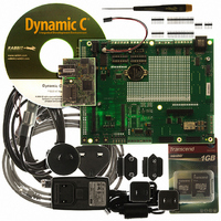
RCM3900 DEV KIT UNIVERSAL
Manufacturer
Rabbit Semiconductor
Series
RabbitCore 3900r
Type
MPU Moduler
Datasheet
1.20-101-1196.pdf
(168 pages)
Specifications of 101-1226
Contents
RabbitCore Module, Dev. Board, AC Adapter, Cable and Dynamic C® CD-Rom
For Use With/related Products
RCM3900
Lead Free Status / RoHS Status
Lead free / RoHS Compliant
Other names
316-1137


The sample program
ing Board is pressed. Follow the instructions included with the sample program. LED DS1
on the Prototyping Board will light up when sending e-mail. Note that pin PB7 is con-
nected to both switch S2 and to the external I/O bus on the Prototyping Board, and so
switch S2 should not be used with Ethernet operations.
6.6.1 RabbitWeb Sample Programs
The sample programs can be found in the
folder.
•
•
•
RabbitCore RCM3900 User’s Manual
BLINKLEDS.C
which the DS1 and DS2 LEDs on the Prototyping Board blink.
DOORMONITOR.C
in to the RCM3900 Prototyping Board when using this sample program. This program
demonstrates adding and monitoring passwords entered via the LCD/keypad module.
SPRINKLER.C
puts in a 24-hour period using the Prototyping Board.
The Web page uses the following setup.
The
the corresponding scripting features.
The real-time clock must be set before you compile and run this sample program — see
Section 3.2.4 for information on sample programs that show how to set the real-time
clock.
Once you compile and run this sample program, open the Web page, enter the times for
the various zones and stations, then press the
You may connect Rabbit’s Demonstration Board to the Prototyping Board's relay and
two outputs to view the on and off intervals via the LEDs on the Demonstration Board.
The Demonstration Board is not included with the Development Kit, but may be pur-
chased separately
Station 1 is connected to the relay on Prototyping Board header J17.
Station 2 is connected to OUT00 on Prototyping Board header J10.
Station 3 is connected to OUT01 on Prototyping Board header J10.
Zones 1, 2 and 3 are watering areas where stations are turned on or off at different times.
Pages/sprinkler.zhtml
—This program demonstrates a basic example to change the rate at
—This program demonstrates how to schedule times for the digital out-
—The optional LCD/keypad module (see Appendix C) must be plugged
SMTP.C
allows you to send an e-mail when a switch on the Prototyp-
page associated with this sample program demonstrates
SAMPLES\RCM3900\TCPIP\RABBITWEB
Submit
button to update the settings.
69
Related parts for 101-1226
Image
Part Number
Description
Manufacturer
Datasheet
Request
R

Part Number:
Description:
COMPUTER SNGLBD BL2120 FRCTNLOCK
Manufacturer:
Rabbit Semiconductor
Datasheet:

Part Number:
Description:
KIT APPLCTN RABBITCORE RCM4010
Manufacturer:
Rabbit Semiconductor
Datasheet:

Part Number:
Description:
KIT MESH NETWORK ADD-ON RCM4510W
Manufacturer:
Rabbit Semiconductor
Datasheet:

Part Number:
Description:
KIT DEV FOR BL2500 COYOTE
Manufacturer:
Rabbit Semiconductor
Datasheet:

Part Number:
Description:
KIT APPLICATION SIMPLE SENSOR
Manufacturer:
Rabbit Semiconductor
Datasheet:

Part Number:
Description:
KIT DEV RABBITCORE RCM3750
Manufacturer:
Rabbit Semiconductor
Datasheet:

Part Number:
Description:
KIT DEV RABBIT 2000 INT'L
Manufacturer:
Rabbit Semiconductor
Datasheet:
Part Number:
Description:
KIT DEV RABBIT RCM2000 INT'L
Manufacturer:
Rabbit Semiconductor
Datasheet:

Part Number:
Description:
KIT DEVELOPMENT RCM3700 INT'L
Manufacturer:
Rabbit Semiconductor
Datasheet:
Part Number:
Description:
MODULE RABBITCORE RCM3720
Manufacturer:
Rabbit Semiconductor
Datasheet:
Part Number:
Description:
MODULE RABBITCORE RCM3220
Manufacturer:
Rabbit Semiconductor
Datasheet:
Part Number:
Description:
MODULE RABBITCORE RCM3210
Manufacturer:
Rabbit Semiconductor
Datasheet:
Part Number:
Description:
COMPUTER SGL-BOARD OP6600 W/SRAM
Manufacturer:
Rabbit Semiconductor
Datasheet:
Part Number:
Description:
COMPUTER SGL-BD BL2000 SRAM/FLSH
Manufacturer:
Rabbit Semiconductor