761135 Spectrum Digital Inc, 761135 Datasheet
761135
Specifications of 761135


Related parts for 761135


761135 Summary of contents
Page 1
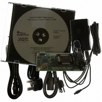
TM eZdsp F28335 2007 Technical Reference DSP Development Systems ...
Page 2
...
Page 3
Technical Reference SPECTRUM DIGITAL, INC. 12502 Exchange Dr., Suite 440 Stafford, TX. 77477 Tel: 281.494.4505 sales@spectrumdigital.com TM F28335 510195-0001 Rev. C November 2007 Fax: 281.494.5310 www.spectrumdigital.com ...
Page 4
Spectrum Digital, Inc. reserves the right to make changes to its products or to discontinue any product or service without notice. Customers are advised to obtain the latest version of relevant information to verify data being relied on is current ...
Page 5
Introduction to the eZdsp Provides a description of the eZdsp 1.0 Overview of the eZdsp 1.1 Key Features of the eZdsp 1.1.1 Hardware Features 1.1.2 Software Features 1.2 Functional Overview of the eZdsp TM 2 Operation of the eZdsp ...
Page 6
Switches . . . . . . . . . . . . . . . . . . . . . . . . . . . . . . . . . . . . . . ...
Page 7
List of Figures TM Figure 1-1, Photo eZdsp F28335 Figure 1-2, Block Diagram eZdsp TM Figure 2-1, eZdsp F28335 PCB Outline (Top) TM Figure 2-2, eZdsp F28335 PCB Outline (Bottom) TM Figure 2-3, eZdsp F28335 Memory Space Figure 2-4, P1 ...
Page 8
List of Tables Table 2-1, External Chip Select and Usages TM Table 2-2, eZdsp F28335 Connectors Table 2-3, P1, JTAG Interface Connector Table 2-4, P2, Expansion Interface Connector Table 2-5, P4, I/O Connectors Table 2-6, P8, I/O Connectors Table 2-7, ...
Page 9
About This Manual This document describes board level operations of the eZdsp Texas Instruments TMS320F28335 Digital Signal Controller (DSC). TM The eZdsp F28335 is a stand-alone module permitting engineers and software developers evaluation of certain characteristics of the TMS320F28335 DSC ...
Page 10
Table 1: Manual History Revision A Production Release B Updated Figures, Text, Schematics C Updated Figures, Tables, Text Table 2: Board History PWB Revision A Production Release B Updated Silk-screen History History ...
Page 11
Introduction to the eZdsp This chapter provides a description of the eZdsp TMS320F28335 Digital Signal Controller, key features, and block diagram of the circuit board. Topic 1.0 Overview of the eZdsp 1.1 Key Features of the eZdsp 1.1.1 Hardware Features ...
Page 12
Spectrum Digital, Inc TM 1.0 Overview of the eZdsp TM The eZdsp F28335 is a stand-alone card--allowing developers to evaluate the TMS320F28335 digital signal controller (DSC) to determine if it meets their application requirements. Furthermore, the module is an excellent ...
Page 13
Key Features of the eZdsp 1.1.1 Hardware Features TM The eZdsp F28335 has the following features: • TMS320F28335 Digital Signal Controller • 150 Mhz. operating speed • On chip 32-bit floating point unit • 68K bytes on-chip RAM • ...
Page 14
Spectrum Digital, Inc 1.2 Functional Overview of the eZdsp Figure 1-1 shows a block diagram of the basic configuration for the eZdsp The major interfaces of the eZdsp are the JTAG interface, and expansion interface USB PORT/JTAG ...
Page 15
Operation of the eZdsp This chapter describes the operation of the eZdsp interfaces and includes a circuit board outline. Topic TM 2.0 The eZdsp F28335 Operation TM 2.1 The eZdsp F28335 Board 2.1.1 Power Connector TM 2.2 eZdsp F28335 Memory ...
Page 16
Spectrum Digital, Inc Topic TM 2.4 eZdsp F28335 Jumpers 2.4.1 JP1, ADCREFIN Select 2.4.2 JR2, XTPD Voltage Select 2.4.3 JR4, Connector P4, P8 Voltage Select 2.4.4 JR5, Connector P2, P10 Voltage Select 2.4.5 JR6, MUX GPIO22_24 Select 2.4.6 JP7, CANA ...
Page 17
TM 2.0 The eZdsp F28335 Operation This chapter describes the eZdsp Information on the eZdsp’s various interfaces is also included. The eZdsp consists of four major blocks of logic: TM 2.1 The eZdsp F28335 Board TM The eZdsp F28335 is ...
Page 18
Spectrum Digital, Inc Figure 2-2 shows the layout of the bottom side of the F28335 eZdsp. JR6 JR4 Figure 2-2, eZdsp 2.1.1 Power Connector TM The eZdsp F28335 is powered Volt only power supply, included with the ...
Page 19
TM 2.2 eZdsp F28335 Memory The eZdsp includes the following on-chip memory: • 256K x 16 Flash • 8 blocks single access RAM (SARAM) • 2 blocks SARAM • 2 blocks of ...
Page 20
Spectrum Digital, Inc 2.2.1 Memory Map The figure below shows the memory map configuration on the eZdsp Figure 2-3, eZdsp Note: The on-chip flash memory has a security key which can prevent visibility when enabled. 2-6 TM F28335 Memory Space ...
Page 21
TM 2.3 eZdsp F28335 Connectors TM The eZdsp F28335 has fourteen connectors. The function of each connector is shown in the table below: TM Table 2: eZdsp F28335 Connectors Connector Function P1 JTAG Interface P2 Expansion P4/P8/P7 I/O Interface P5/P9 ...
Page 22
Spectrum Digital, Inc 2.3.1 P1, JTAG Interface TM The eZdsp F28335 is supplied with a 14-pin header interface, P1. This is the standard interface used by JTAG emulators to interface to Texas Instruments DSPs. The positions of the 14 pins ...
Page 23
P2, Expansion Interface The positions of the 60 pins on the P2 connector are shown in the figure below Figure 2-5, Connector P2 Pin Locations The definition of P2, which has the I/O signal interface is shown ...
Page 24
Spectrum Digital, Inc 2.3.3 P4/P8/P7, I/O Interface The connectors P4, P8, and P7 present the I/O signals from the DSC. The layout of these connectors are shown below. The pin definition of the P4 connector is shown in the table ...
Page 25
The pin definition of the P8 connector is shown in the table below. Pin # Signal 1 +3.3V/+5V/ MUX_GPIO29_SCITXDA_XA19 5 GPIO14_TZ3n_XHOLD_SCITXDB_MCLKXB 7 GPIO21_EQEP18_MDRA_CANRXB 9 GPIO0_EPWM1A 11 GPIO2_EPWM2A 13 GPIO4_EPWM3A 15 GPIO27_ECAP4_EQEP2S_MFSXB 17 GPIO13_TZ2N_CANRXB_MDRB 19 GND 21 GPIO7_EPWM4B_MCLKRA_ECAP2 23 ...
Page 26
Spectrum Digital, Inc 2.3.4 P5/P9, Analog Interface The position of the 30 pins on the P5/P9 connectors are shown in the diagram below as viewed from the top of the eZdsp. The definition of P5/P9 signals are shown in the ...
Page 27
P6, Power Connector Power (5 volts) is brought onto the eZdsp connector has an outside diameter of 5.5 mm. and an inside diameter of 2.5 mm. The position of the P6 connector is shown below. The diagram of P6, ...
Page 28
Spectrum Digital, Inc 2.3.6 P10, Expansion Interface The positions of the 60 pins on the P10 connector are shown in the figure below. eZdsp TMS320F28335 Pin 2 Pin 1 Figure 2-10, Connector P10 Pin Locations The definition of P10, which ...
Page 29
P11, CANA Connector The eZdsp F28335 has a 9 Pin female D-connector which brings out the CANA transmit and receive signals. This CAN interface uses the SN65HVD235 CAN driver. The pin positions for the P11 connector as viewed from ...
Page 30
Spectrum Digital, Inc 2.3.8 P12, RS-232 Connector The eZdsp F28335 has an RS-232 connector which brings out the SCIA transmit and receive signals to be used as UART. This UART uses the MAX3238 RS-232 line driver and is routed to ...
Page 31
J11, CANB Header The CANB signals are routed through the SN65HVD235 CAN driver double row header, J11. The pin numbers for J11 and their corresponding signals are shown in the table ...
Page 32
Spectrum Digital, Inc 2.3.10 J12, SCIB Header The SCIB signals are routed through the MAX3238 line driver double row header, J10. The pin numbers for J12 and their corresponding signals are shown ...
Page 33
Connector Part Numbers The table below shows the part numbers for connectors which can be used on the TM eZdsp F28335. Part numbers from other manufacturers may also be used. Table 15: eZdsp Connector P1 SAMTEC TSW-1-10-07-G-T P2 SAMTEC ...
Page 34
Spectrum Digital, Inc 2.4.1 JP1, ADCREFIN Select Jumper JP1 is used to connect the output of U29, REF3020 to ADCREFIN. When the jumper is shorted the +2.048 voltage level is routed to the ADCREFIN signal of the DSC. When the ...
Page 35
JR4, Connector P4, P8 Voltage Select Jumper JR4 is a surface mount jumper located on the bottom side of the board. To use a configuration a zero ohm resistor should be used for shorting. This jumper allows the user ...
Page 36
Spectrum Digital, Inc 2.4.5 JR6, MUX GPIO22_24 Select Jumper JR6 is a surface mount jumper located on the bottom side of the board. To use a configuration a zero ohm resistor should be used for shorting. This jumper is used ...
Page 37
JP8, CANB Termination Resistor Select Jumper JP8 is used to select the termination resistor on the CANB interface. When installed a termination resistor is placed between pins 3 and 4 of the connector J11. This jumper is installed at ...
Page 38
Spectrum Digital, Inc 2.6 Switches TM The eZdsp F28335 has two switches. SW1 is used to select the power on boot load options. SW2 is used to select the processor configuration. 2.6.1 SW1, Boot Load Option Switch Switch SW1 is ...
Page 39
SW2, Processor Configuration Switch Switch SW2 is used to select the processor configuration. The eZdsp supports 2 on board SCI ports and 2 on board CAN ports. These ports can be used on board or routed to expansion connectors. ...
Page 40
Spectrum Digital, Inc 2.7 Test Points TM The eZdsp F28335 has fifteen test points. Their location on the bottom of the board are shown in the figure below. TP1 TP4 TP3 Figure 2-24, eZdsp 2-26 TM F28335 Test Points (Bottom) ...
Page 41
The signals each test point is tied to is listed in the table below. Table 27: Test Points Test Point TP1 TP2 TP3 TP4 Spectrum Digital, Inc Signal AGND XCLKOUT U8(DSP) Pin 81, TEST1 U8(DSP) Pin 82, TEST2 2-27 ...
Page 42
Spectrum Digital, Inc 2-28 TM eZdsp F28335 Technical Reference ...
Page 43
TM The schematics for the eZdsp that accompanies this board. The schematics were drawn on ORCAD. The schematics are correct for both the socketed and unsocketed version TM of the eZdsp . The TMS320F28335 supports +3.3V Input/Output levels which are ...
Page 44
Spectrum Digital, Inc A-2 TM eZdsp F28335 Technical Reference ...
Page 45
VDD(1V8).12 167 VDD(1V8).12 154 VDD(1V8).11 146 VDD(1V8).10 139 VDD(1V8).9 126 VDD(1V8).8 117 VDD(1V8).7 109 VDD(1V8).6 101 VDD(1V8).5 61 VDD(1V8).4 29 VDD(1V8).3 23 VDD(1V8).2 15 VDD(1V8).1 4 VDDIO(3V3).8 170 VDDIO(3V3).7 159 VDDIO(3V3).6 143 VDDIO(3V3).5 121 VDDIO(3V3).4 107 VDDIO(3V3).3 93 VDDIO(3V3).2 71 ...
Page 46
Spectrum Digital, Inc A-4 TM eZdsp F28335 Technical Reference ...
Page 47
Spectrum Digital, Inc A-5 ...
Page 48
Spectrum Digital, Inc A-6 VSS2 34 VSS1 12 VDD2 33 VDD1 11 TM eZdsp F28335 Technical Reference ...
Page 49
Spectrum Digital, Inc A-7 ...
Page 50
Spectrum Digital, Inc A eZdsp F28335 Technical Reference ...
Page 51
B 2 Spectrum Digital, Inc A-9 ...
Page 52
Spectrum Digital, Inc eZdsp F28335 Technical Reference ...
Page 53
Spectrum Digital, Inc A-11 ...
Page 54
Spectrum Digital, Inc A- eZdsp F28335 Technical Reference ...
Page 55
THERMAL_PAD Spectrum Digital, Inc A-13 ...
Page 56
Spectrum Digital, Inc J12 A-14 J11 TM eZdsp F28335 Technical Reference ...
Page 57
J12 J11 Spectrum Digital, Inc A-15 ...
Page 58
Spectrum Digital, Inc A-16 TM eZdsp F28335 Technical Reference ...
Page 59
MechanicaI Information This appendix contains the mechanical information about the socketed and unsocketed versions of the eZdsp Appendix B TM eZdsp F28335 TM F28335 B-1 ...
Page 60
Spectrum Digital, Inc B-2 TM eZdsp F28335 Technical Reference ...
Page 61
Spectrum Digital, Inc B-3 ...
Page 62
Spectrum Digital, Inc B-4 TM eZdsp F28335 Technical Reference ...
Page 63
...
Page 64
Printed in U.S.A., November 2007 510195-0001 Rev. C ...