101-1147 Rabbit Semiconductor, 101-1147 Datasheet - Page 2
101-1147
Manufacturer Part Number
101-1147
Description
KIT RIO PROGRAM I/O
Manufacturer
Rabbit Semiconductor
Series
Rabbit® RIO™r
Type
MPU Moduler
Datasheet
1.101-1147.pdf
(4 pages)
Specifications of 101-1147
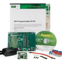
Contents
RabbitCore Module, Dev. Board, AC Adapter, Cable and Dynamic C® CD-Rom
Processor To Be Evaluated
RCM4100
Data Bus Width
8 bit
Interface Type
SPI
Silicon Manufacturer
Rabbit
Silicon Family Name
Rabbitcore
Kit Contents
Board
Features
Multiple Communication Interfaces
Development Tool Type
Hardware / Software - Dev Kit (Dev Tool)
Rohs Compliant
Yes
For Use With/related Products
RCM4100
Lead Free Status / RoHS Status
Vendor undefined / Vendor undefined


Hardware Connections
1. Prepare the Prototyping Board for
Development
Snap in four of the plastic standoffs supplied in the bag
of accessory parts from the RIO Programmable I/O Kit
in the holes at the corners as shown.
2. Attach Module to Prototyping Board
Turn the RCM4110 module so that the mounting holes
of the RCM4110 line up with the corresponding holes
on the Prototyping Board. Insert the metal standoffs as shown in Figure 2, secure them from the bottom of
the Prototyping Board using the 4-40 × 3/16 screws, then insert the module’s header J3 on the bottom side
into header socket RCM1 on the Prototyping Board.
Press the module’s pins gently into the Prototyping Board header socket—press down in the area above
the header pins. For additional integrity, you may secure the RCM4110 to the standoffs from the top
using the remaining two 4-40 × 3/16 screws.
3. Set Jumpers
Jumpers were placed at the factory on Prototyping Board headers J2, J7, J8, J9, and J15 as shown in Figure 3
to set up the Prototyping Board for the SPI serial mode used with the sample programs. Application Note
AN415, RIO Programmable I/O Kit, describes other configuration options.
4. Connect Programming Cable
The programming cable connects the RCM4110 to the PC running Dynamic C to download programs
and to monitor the RCM4110 module during debugging.
Connect the 10-pin connector of the programming cable labeled PROG to header J1 on the RCM4110
as shown in Figure 3. Be sure to orient the marked (usually red) edge of the cable towards pin 1 of the
connector. (Do not use the DIAG connector, which is used for a normal serial connection to Serial Port A.)
NOTE: It is important that you line up the pins on header J3 of the RCM4110 module exactly with
socket RCM1 on the Prototyping Board. The header pins may become bent or damaged if the pin
alignment is offset, and the module will not work. Permanent electrical damage to the module may
also result if a misaligned module is powered up.
Figure 2. Install the RCM4110 Module on the Prototyping Board
Figure 1. Insert Plastic Standoffs
Related parts for 101-1147
Image
Part Number
Description
Manufacturer
Datasheet
Request
R

Part Number:
Description:
KIT DEV FOR BL2500 COYOTE
Manufacturer:
Rabbit Semiconductor
Datasheet:

Part Number:
Description:
KIT APPLICATION SIMPLE SENSOR
Manufacturer:
Rabbit Semiconductor
Datasheet:

Part Number:
Description:
KIT DEV RABBITCORE RCM3750
Manufacturer:
Rabbit Semiconductor
Datasheet:

Part Number:
Description:
KIT DEV RABBIT 2000 INT'L
Manufacturer:
Rabbit Semiconductor
Datasheet:
Part Number:
Description:
KIT DEV RABBIT RCM2000 INT'L
Manufacturer:
Rabbit Semiconductor
Datasheet:

Part Number:
Description:
KIT DEVELOPMENT RCM3700 INT'L
Manufacturer:
Rabbit Semiconductor
Datasheet:

Part Number:
Description:
BL4S200 TOOL KIT
Manufacturer:
Rabbit Semiconductor
Datasheet:


Part Number:
Description:
KIT DEVELOPMENT FOR JACKRABBIT
Manufacturer:
Rabbit Semiconductor
Part Number:
Description:
MODULE RABBITCORE RCM3720
Manufacturer:
Rabbit Semiconductor
Datasheet:
Part Number:
Description:
MODULE RABBITCORE RCM3220
Manufacturer:
Rabbit Semiconductor
Datasheet:
Part Number:
Description:
MODULE RABBITCORE RCM3210
Manufacturer:
Rabbit Semiconductor
Datasheet:
Part Number:
Description:
COMPUTER SGL-BOARD OP6600 W/SRAM
Manufacturer:
Rabbit Semiconductor
Datasheet:
Part Number:
Description:
COMPUTER SGL-BD BL2000 SRAM/FLSH
Manufacturer:
Rabbit Semiconductor