C8051F360-TB Silicon Laboratories Inc, C8051F360-TB Datasheet
C8051F360-TB
Specifications of C8051F360-TB


Related parts for C8051F360-TB

C8051F360-TB Summary of contents
Page 1
... Notes: The target board included in this kit is provided with a pre-soldered C8051F360 MCU (LQFP48 package). Code developed on the C8051F360 can be easily ported to the other members of this MCU family. Refer to the C8051F36x data sheet for the differences between the members of this MCU family. ...
Page 2
... To complete the installation process, connect the included USB cable between the host computer and the USB connector (P4) on the C8051F360 target board. Windows will automatically finish the driver installation. Information windows will pop up from the taskbar to show the installation progress. ...
Page 3
... Tasking Hi-Tech SDCC The demo applications for the C8051F360 target board are written to work with the Keil and SDCC toolsets. 4.2. Keil Evaluation Toolset 4.2.1. Keil Assembler and Linker The assembler and linker that are part of the Keil Demonstration Toolset are the same versions that are found in the full Keil Toolset. The complete assembler and linker reference manual can be found on-line under the Help menu in the IDE or in the “ ...
Page 4
C8051F36x-DK 4.3. Configuration Wizard 2 The Configuration Wizard code generation tool for all of the Silicon Laboratories devices. Code is generated through the use of dialog boxes for each of the device's peripherals. Figure 1. Configuration Wizard ...
Page 5
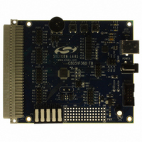
... P3.0 P3.1 RESET P1 PORT_4 J12 J14 J13 P3.0 P3.1 J6 P3.2 P3.3 PORT_3 P0.1 P0.2 SILICON LABS P3.4 P3.5 www.silabs.com C8051F360 TB J5 PORT_2 F360 J15 U1 J4 PORT_0 J16 PORT_1 J11 J10 Target Board Figure 2. Hardware Setup using a USB Debug Adapter D4 USB ACTIVE ...
Page 6
C8051F36x-DK 6. Using the Keil Software 8051 Tools with the Silicon Laboratories IDE To perform source-level debugging with the IDE, you must configure the Keil 8051 tools to generate an absolute object file in the OMF-51 format with object extensions ...
Page 7
... Port I/O crossbar, configuring a timer for an interrupt routine, initializing the system clock, and configuring a GPIO port. When compiled/assembled and linked, this program flashes the green LED on the C8051F360 target board about five times a second using the interrupt handler with a timer. ...
Page 8
... C8051F36x-DK 8. Target Board The C8051F36x Development Kit includes a target board with a C8051F360 device pre-installed for evaluation and preliminary software development. Numerous input/output (I/O) connections are provided to facilitate prototyping using the target board. Refer to Figure 3 for the locations of the various I/O connectors. ...
Page 9
... Switches and LEDs Three switches are provided on the target board. Switch RESET is connected to the RESET pin of the C8051F360. Pressing RESET puts the device into its hardware-reset state. Switches P3.0 and P3.1 are connected to the C8051F360’s general purpose I/O (GPIO) pins through headers. Pressing P3.0 or P3.1 generates a logic low signal on the port pin ...
Page 10
... Table 2. J12–J19 Port Connector Pin Descriptions Pin # 8.4. Target Board DEBUG Interface (J9) The DEBUG connector (J9) provides access to the DEBUG (C2) pins of the C8051F360 used to connect the Serial Adapter or the USB Debug Adapter to the target board for in-circuit debugging and Flash programming. Table 3 shows the DEBUG pin definitions. ...
Page 11
... The RX, TX, CTS and RTS signals of the UART side of the Bridge (CP2102) may be connected to the microcontroller by installing shorting blocks on J12 as follows: 8.6. Analog I/O (P2) Several of the C8051F360 target device’s port pins are connected to the P3 terminal block. Refer to Table 5 for the P3 terminal block connections. Table 5. J6 Terminal Block Pin Descriptions Pin # 8 ...
Page 12
C8051F36x-DK 9. Schematics 12 Rev. 0.2 ...
Page 13
C8051F36x-DK Rev. 0.2 13 ...
Page 14
C8051F36x- OTES 14 Rev. 0.2 ...
Page 15
OCUMENT HANGE IST Revision 0.1 to Revision 0.2 Added Relevant Devices section. Section 2 moved to Section 5. Change section 3 to "Getting Started." Updated section 3 to include latest VCP driver installation instructions. Changed section 4 ...
Page 16
... Should Buyer purchase or use Silicon Laboratories products for any such unintended or unauthorized ap- plication, Buyer shall indemnify and hold Silicon Laboratories harmless against all claims and damages. Silicon Laboratories and Silicon Labs are trademarks of Silicon Laboratories Inc. Other products or brandnames mentioned herein are trademarks or registered trademarks of their respective holders. ...