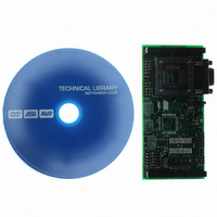
ATSTK501 Atmel, ATSTK501 Datasheet - Page 10

ATSTK501
Manufacturer Part Number
ATSTK501
Description
ADAPTER KIT FOR 64PIN AVR MCU
Manufacturer
Atmel
Datasheet
1.ATSTK501.pdf
(29 pages)
Specifications of ATSTK501
Accessory Type
STK500 Expansion Module
Processor To Be Evaluated
ATmega103 and ATmega128
Data Bus Width
8 bit
Interface Type
RS-232
For Use With/related Products
64-pin megaAVR Devices
For Use With
ATADAPCAN01 - EXTENSION CAN ADD-ON TO STK500/1ATSTK500 - PROGRAMMER AVR STARTER KIT
Lead Free Status / RoHS Status
Lead free / RoHS Compliant
Other names
Q1167170
STK501
STK501
STK501
STK501
Using the STK501 Top Module
2.3.2
2-4
High-voltage
Programming
Figure 2-5. In-System Programming
To program the ATmega103(L) or ATmega128(L) using High-voltage (Parallel) Pro-
gramming, connect the PROGCTRL to PORTD and PROGDATA to PORTB on the
STK500 as shown in Figure 2-6.
As described in the STK500 User Guide, the BSFL2 jumper must be mounted when
High-voltage Programming ATmega devices. This also applies to the High-voltage Pro-
gramming of ATmega103(L) and ATmega128(L).
The device can now be programmed using the High-voltage Programming mode in AVR
Studio STK500 software.
Note:
Note:
Caution: Make sure the SRAM (if mounted) can handle this voltage.
See the STK500 User Guide for information on how to use the STK500 front-
end software in High-voltage Programming mode.
For the High-voltage Programming mode to function correctly, the target voltage
must be higher than 4.5V.
AVR
®
STK501 User Guide


