TC642DEMO Microchip Technology, TC642DEMO Datasheet - Page 13
TC642DEMO
Manufacturer Part Number
TC642DEMO
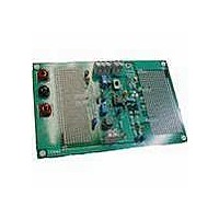
Description
DEMO BOARD FOR TC642/46/47/48/49
Manufacturer
Microchip Technology
Datasheet
1.TC642DEMO.pdf
(14 pages)
Specifications of TC642DEMO
Processor To Be Evaluated
TC642 and TC646
Lead Free Status / RoHS Status
Lead free / RoHS Compliant
Lead Free Status / RoHS Status
Lead free / RoHS Compliant, Lead free / RoHS Compliant


M
B.1
TABLE B-1:
C
C
C
C
C
C
C
C
LED
Q
Q
Q
R
R
R
R
R
R
U
Component
2003 Microchip Technology Inc.
1
2
3
4
5
6
7
8
1
3
5
6
7
8
1
1
3
4
, R
, R
, Q
2
4
2
DEMO BOARD COMPONENTS
10 µF Radial Electrolytic
Capacitor
0.01 µF Ceramic Disk Capacitor
0.01 µF Ceramic Disk Capacitor
1.0 µF Ceramic Capacitor
Not used
0.1 µF Ceramic Disk Capacitor
0.47 µF to 1 µF Radial
Electrolytic Capacitor
0.01 µF Ceramic Disk Capacitor
10 mA Miniature LED
2N2222A NPN Transistor
See Applications section of
TC64X and TC64XB data
sheets.
2N3906 (or Equivalent) PNP
Transistor
See the Applications section of
the TC64X and TC64XB data
sheets.
See the Applications section of
the TC64X and TC64XB data
sheets.
See the Applications section of
the TC64X and TC64XB data
sheets.
See Applications section of the
TC64X and TC64XB data
sheets.
1.2 k , 1/4 Watt, 5% Resistor
470
TC642/B, TC646/B, TC647/B,
TC648/B or TC649/B Fan
Control devices
FAN CONTROL MODULE COMPONENTS LIST
1/4 Watt, 5% Resistor
Appendix B. Bill-of-Materials (BOM)
Table B-1 lists typical components and the associated values that comprise the
TC64X/TC64XB Fan Control Demo Board.
Typical Value
TC64X/TC64XB FAN CONTROL DEMO
Power supply filter.
Bypass capacitor.
Bypass capacitor.
PWM capacitor. Typical value is 1.0 µF (PWM frequency of 30 Hz).
—
SENSE input coupling capacitor.
Fan acoustic noise suppression capacitor. (Optional)
Bypass capacitor.
LED lights when FAULT output is LOW (active). (Optional)
Darlington pair output option. If used, Q3 location MUST be left
open.
Single transistor output option. Can be bipolar transistor or logic
level MOSFET (depending on cost constraints and fan current). If
used, Q
LED Driver transistor (Optional).
Value depends on the type of sensor used and the desired fan
speed vs. temperature profile.
Value depends on the desired minimum fan speed setting
(TC642/2B, TC647/7B) or auto-shutdown temperature (TC646/6B,
TC648/8B, TC649/9B).
Base current limiting resistor. Value depends on the type of fan and
driver used. Typical values appear in Table B-1.
Fan Current sensing resistor. Value depends on full-speed fan
current. Typical values are shown in Table B-1.
LED Drive transistor base resistor (Optional).
LED Drive transistor series-limiting resistor (Optional).
1
and Q
2
locations MUST be left open.
BOARD USER’S GUIDE
Comments
DS21401C-page 9
Related parts for TC642DEMO
Image
Part Number
Description
Manufacturer
Datasheet
Request
R

Part Number:
Description:
KIT EVALUATION FOR TC642
Manufacturer:
Microchip Technology
Datasheet:

Part Number:
Description:
Manufacturer:
Microchip Technology Inc.
Datasheet:
Part Number:
Description:
Manufacturer:
Microchip Technology Inc.
Datasheet:
Part Number:
Description:
Manufacturer:
Microchip Technology Inc.
Datasheet:
Part Number:
Description:
Manufacturer:
Microchip Technology Inc.
Datasheet:
Part Number:
Description:
Manufacturer:
Microchip Technology Inc.
Datasheet:
Part Number:
Description:
Manufacturer:
Microchip Technology Inc.
Datasheet:
Part Number:
Description:
Manufacturer:
Microchip Technology Inc.
Datasheet:
Part Number:
Description:
Manufacturer:
Microchip Technology Inc.
Datasheet: