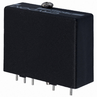
6421 Crydom Co., 6421 Datasheet - Page 2

6421
Manufacturer Part Number
6421
Description
I/O MODULE2.4-6V SIP DC INPUT
Manufacturer
Crydom Co.
Series
6r
Type
ACr
Datasheet
1.6421.pdf
(2 pages)
Specifications of 6421
Color
Black
Style
Standard
Voltage - Input
5VDC (3.5 ~ 6VDC)
Current - Input
20mA
Voltage - Output
12 ~ 140VAC (120VAC Nom)
Current - Output
0.02 ~ 3.5A
Turn On Time
1/2 Cycle
Turn Off Time
1/2 Cycle
Features
Hold Down Screw
Leaded Process Compatible
No
No. Of Analog Outputs
1
No. Of Digital Inputs
1
Output Voltage Min
12V
Supply Voltage Min
2.4VDC
Output Current Max
3.5A
Signal Input Type
3.5 To 6VDC
Output Type
AC
Input Type
DC
Input Voltage (max)
5V
Output Voltage (max)
140V
Input Current (max)
20mA
Output Current
3.5A
Isolation Voltage
4kV
Output Device
Triac
Pin Count
5
Mounting
Through Hole
Operating Temp Range
-40C to 80C
Operating Temperature Classification
Commercial
Rad Hardened
No
Lead Free Status / RoHS Status
Lead free / RoHS Compliant
Lead Free Status / RoHS Status
Lead free / RoHS Compliant, Lead free / RoHS Compliant
Other names
CC1243
Available stocks
Company
Part Number
Manufacturer
Quantity
Price
Company:
Part Number:
642179
Manufacturer:
MOLEX
Quantity:
35 000
Company:
Part Number:
64219710
Manufacturer:
DELPHI
Quantity:
40 000
BUFFERED OUTPUT MODULES
A buffered non-inverting module turns on when pin 4 is held in the
low state (logic 0), the same as standard modules driven in the sink
mode. A buffered inverting module conversely turns on when pin 4
is held high (logic 1). In the absence of an input signal and/or logic
supply (open Circuit), all models will be in the off-state.
Buffered modules may be used with standard 5 pin PB or MS
mounting boards. However, the 3.3K pull-up resistor will add to the
logic drive current of a non-inverting module and may be removed.
For an inverting module, the resistor must be removed to avoid a
false “on” command, unless a “normally closed” condition is desir-
able for use with a ground seeking (logic 0) signal source.
3.0
2.5
2.0
1.5
1.0
3.5
0
FastFax Document No. 308
081398, PAGE 2 OF 2
C U R R E N T D E R AT I N G C U RV E
Max. Load Current vs. Temp.
AMBIENT TEMPERATURE (ºC)
20
40
60
80
AC Output Buffered Modules
For recommended applications and more information contact:
USA: (800) 8 CRYDOM • (800) 827-9366 • (619) 715-7200 • fax (619) 715-7280
Crydom Corp, 9525 Chesapeake Drive, San Diego, CA 92123 • e-mail: sales@crydom.com
WEB SITE: http://www.crydom.com FASTFAX Product Information: (888) 267-9191
UK: (44)1202 812300 • fax (44)1202 812340 Crydom International Ltd., 85, Condor Close,
Woolsbridge Industrial Estate, Three-Legged Cross. Wimborne, Dorset, England BH21 6SU
GERMANY: (49) (0)6874 182580 • fax (49)(0)6874 182585 Crydom GmbH,
Gewerbegebiet Im Schachen, D-66687 Nunkirchen, Germany • e-mail: vertrieb@crydom.com
GENERAL SPECIFICATIONS
Min. Dielectric Input/Output (1 Minute)
Min. Isolation Resistance Input/Output (@ 500V)
Capacitance input to output
Temperature Range — Operating
Temperature Range — Storage
DC LOGIC
SUPPLY
DC LOGIC INPUT
STATUS
COM (-)
#4-40. PHILLIPS
LED
DOWN SCREW
.040 (1.0) DIA.
HEAD HOLD
(5 PLACES)
CAPTIVE
©1998 CRYDOM CORP Specifications subject to change without notice.
(+)
(31.7)
W I R I N G & M E C H A N I C A L D I A G R A M S
1.25
(6.3)
.25
3
4
5
All dimensions are in inches (millimeters)
INV or
NON-INV
LOGIC
5
4
3
BOTTOM VIEW
(40.6)
1.60
(35.5)
1.40
(43.1)
1.70
2
(30.5)
1.20
Zero
Switch
(25.4)
1.00
(17.8)
1
.70
(7.6)
.30
-40˚ C to 125˚ C
-40˚ C to 80˚ C
4,000 VRMS
10
(2.5)
.100
(7.6)
.30
10
8 pF
Ohms
(15.2)
AC
OUTPUT
1
2
.60
LOAD
~
9002


