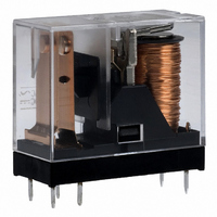
G2R-1A-E-DC12 Omron, G2R-1A-E-DC12 Datasheet - Page 20
G2R-1A-E-DC12
Manufacturer Part Number
G2R-1A-E-DC12
Description
RELAY PWR SPST-NO 16A 12VDC
Manufacturer
Omron
Series
G2Rr
Datasheets
1.G2R-1A-E-DC12.pdf
(14 pages)
2.G2R-1A-E-DC12.pdf
(30 pages)
3.G2R-2-SND_DC24S.pdf
(19 pages)
Specifications of G2R-1A-E-DC12
Relay Type
General Purpose
Coil Resistance
275 Ohms
Contact Form
SPST-NO (1 Form A)
Contact Rating (current)
16A
Switching Voltage
380VAC, 125VDC - Max
Coil Type
Standard
Coil Current
43.6mA
Coil Voltage
12VDC
Turn On Voltage (max)
8.4 VDC
Turn Off Voltage (min)
1.8 VDC
Mounting Type
Through Hole
Termination Style
PC Pin
Circuit
SPST-NO (1 Form A)
Contact Rating @ Voltage
16A @ 250VAC
Control On Voltage (max)
8.4 VDC
Control Off Voltage (min)
1.8 VDC
Contact Rating
16 A
Contact Termination
Solder Pin
Mounting Style
Through Hole
Power Consumption
530 mW
Contact Material
Silver Alloy
Coil Voltage Vdc Nom
12V
Contact Current Max
16A
Contact Voltage Ac Nom
250V
Contact Voltage Dc Nom
30V
Contact Configuration
SPST-NO
Lead Free Status / RoHS Status
Lead free / RoHS Compliant
Lead Free Status / RoHS Status
Lead free / RoHS Compliant, Lead free / RoHS Compliant
Other names
G2R-1A-E-DC12
G2R1AEDC12
Z2307
G2R1AEDC12
Z2307
Available stocks
Company
Part Number
Manufacturer
Quantity
Price
Company:

Part Number:
G2R-1A-E-DC12V
Manufacturer:
OMRON
Quantity:
12 000
Company:
Part Number:
G2R-1A-E-DC12V
Manufacturer:
OMRON
Quantity:
12 000


Process 6: Cooling
Upon completion of automatic soldering, use a fan or other device to
forcibly cool the PCB. This helps prevent the relay and other compo-
nents from deteriorating due to the inertial heat of soldering.
Fully sealed relays are washable. Do not, however, put fully sealed
relays in a cold cleaning solvent immediately after soldering or the
seals may be damaged.
Process 7: Cleaning
Avoid cleaning the soldered terminals whenever possible. When a
resin-type flux is used, no cleaning is necessary. If cleaning cannot
be avoided, exercise care in selecting an appropriate cleaning sol-
vent.
Note: 1. Consult your OMRON representative before using any other
20
Necessary
Boiling cleaning and
immersion cleaning are not
possible. Clean only the
back of the PCB with a
brush.
Chlorine-based
Water-based
Alcohol-based
Others
Cleaning method
Unsealed
2. Worldwide efforts are being made at discontinuing the use
3. It may be difficult to clean the space between the relay and
4. Ultrasonic cleaning may have an adverse effect on the per-
5. Contact Omron representative for recommended cleaning
Flux protection
cleaning solvent. Do not use Freon-TMC-based, thinner-
based, or gasoline-based cleaning solvents.
of CFC-113-based (fluorochlorocarbon-based) and trichlo-
roethylene-based cleaning solvents. The user is requested
to refrain from using these cleaning solvents
PCB using hydrogen-based or alcohol-based cleaning sol-
vent. It is recommended the stand-off-type be used, such as
G6A-@-ST, when using hydrogen-based or alcohol-based
cleaning solvents.
formance of relays not specifically manufactured for ultra-
sonic cleaning. Please refer to the model number to
determine if your relay is intended to be cleaned ultrasoni-
cally.
procedures of specific relays.
Electromechanical Relays
protection
Solvent
Flux
List of Cleaning Solvents
Perochlene
Chlorosolder
Trichloroethylene
Indusco
Holys
IPA
Ethanol
Thinner
Gasoline
Cleansing Method
Boiling cleaning and immersion clean-
ing are possible. Ultrasonic cleaning
will have an adverse effect on the per-
formance of relays not specifically
manufactured for ultrasonic cleaning.
The washing temperature is 40°C max.
Necessary
Fully sealed
Fully sealed
Yes
Yes
Yes
No
Automatic cleaning
Ultrasonic cleaning
(see note 4)
Technical Information
Fully Seated
Process 8: Coating
Do not apply a coating agent to any flux-resistant relay or relay with a
case because the coating agent will penetrate into the relay and the
contacts may be damaged.
Some coating agents may damage the case of the relay. Be sure to
use a proper coating agent.
Do not fix the position of relay with resin or the characteristics of the
relay will change.
■ Surface Mounting
The following tables list the processes required for mounting a relay
onto a PCB and the points to be noted in each process.
Process 1: Cream Solder Printing
Do not use a cream solder that contains a flux with a large amount of
chlorine or the terminals of the relay may be corroded.
Process 2: Relay Mounting
The holding force of the relay holder must be the same as or more
than the minimum holding force value required by the relay.
Process 3: Transportation
The relay may be dismounted by vibration during transportation. To
prevent this, it is recommended an adhesive agent be applied to the
relay’s gluing part (protruding part) to tack the relay.
Epoxy
Urethane
Silicone
Fluorine
A
B
C
NO
Direction
Dispenser Method
Resin
Adhesive Agent Application Methods
Direction A
200 g max.
500 g max.
200 g max.
Direction C
G6H
YES
YES
NO
YES
YES
Screen-printing Method
Direction B
Fully Sealed
200 g max.
500 g max.
200 g max.
G6S
Related parts for G2R-1A-E-DC12
Image
Part Number
Description
Manufacturer
Datasheet
Request
R

Part Number:
Description:
RELAY
Manufacturer:
Omron
Datasheet:
Part Number:
Description:
RELAY
Manufacturer:
Omron
Datasheet:

Part Number:
Description:
RELAY
Manufacturer:
Omron
Datasheet:
Part Number:
Description:
RELAY
Manufacturer:
Omron
Datasheet:
Part Number:
Description:
RELAY
Manufacturer:
Omron
Datasheet:

Part Number:
Description:
RELAY
Manufacturer:
Omron
Datasheet:
Part Number:
Description:
RELAY
Manufacturer:
Omron
Datasheet:
Part Number:
Description:
RELAY
Manufacturer:
Omron
Datasheet:
Part Number:
Description:
RELAY
Manufacturer:
Omron
Datasheet:
Part Number:
Description:
RELAY
Manufacturer:
Omron
Datasheet:
Part Number:
Description:
RELAY
Manufacturer:
Omron
Datasheet:
Part Number:
Description:
RELAY
Manufacturer:
Omron
Datasheet:
Part Number:
Description:
RELAY
Manufacturer:
Omron
Datasheet:
Part Number:
Description:
RELAY
Manufacturer:
Omron
Datasheet:
Part Number:
Description:
RELAY
Manufacturer:
Omron
Datasheet: