G2R-1-S DC12(S) Omron, G2R-1-S DC12(S) Datasheet - Page 12
G2R-1-S DC12(S)
Manufacturer Part Number
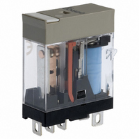
G2R-1-S DC12(S)
Description
RELAY PWR SPDT 10A 12VDC QC MNT
Manufacturer
Omron
Series
G2RSr
Datasheets
1.G2R-1A-E-DC12.pdf
(30 pages)
2.G2R-1A-E-DC12.pdf
(14 pages)
3.G2R-1-S_DC12S.pdf
(12 pages)
Specifications of G2R-1-S DC12(S)
Relay Type
General Purpose
Contact Form
SPDT (1 Form C)
Contact Rating (current)
10A
Switching Voltage
440VAC, 125VDC - Max
Coil Type
Standard
Coil Current
43.2mA
Coil Voltage
12VDC
Turn On Voltage (max)
8.4 VDC
Turn Off Voltage (min)
1.8 VDC
Mounting Type
Socket
Termination Style
Quick Connect - .187" (4.7mm)
Circuit
SPDT (1 Form C)
Contact Rating @ Voltage
10A @ 250VAC
Control On Voltage (max)
8.4 VDC
Control Off Voltage (min)
1.8 VDC
Lead Free Status / RoHS Status
Lead free / RoHS Compliant
Other names
G2R-1-S-DC12S
G2R1SDC12S
Z1632
G2R1SDC12S
Z1632


Relay Driving Signal Waveform
A long rise time and/or fall time of the signal driving the relay may
prolong the operate time and/or release time of the relay. This situa-
tion may shorten the life expectancy of the contacts. If this situation
cannot be avoided, providing a Schmitt trigger circuit at the circuit
stage preceding the relay circuit will shape a waveform with sharp
transitions, as shown in the following diagram:
If the Schmitt trigger circuit is configured of transistors, a residual
voltage may exist in the output of the circuit. Therefore, confirm that
the rated voltage is present across the relay coil, or that the residual
voltage drops to zero when the relay releases.
Cyclic Switching of AC Load
If the relay operates in synchronization with the supply voltage, the
life of the relay may be shortened. When designing the control sys-
tem in which the relay is used, estimate the life of the relay and thus
the reliability of the overall system under actual operating conditions.
Moreover, construct the circuit so that the relay operates in a random
phase or in the vicinity of the zero point.
Dark Current in OFF Time
A circuit that produces a control output as soon as the relay operates
must be carefully designed. In the first example, electrode dark cur-
rent flows as shown when the relay operates. When dark current
flows into the relay coil, the relay’s resistivity to shock and vibration
may degrade.
12
Incorrect
Correct
E
Contact
Vin
AC
Electromechanical Relays
Vin
Vin
Vout
Vin
Waveform
shaping circuit
(Schmitt circuit with inverter)
Vout
Driver circuit
TE
I
LOAD
B
Io
I
C
Technical Information
E
AC
TE
Overcoming Chatter in DC Relays
Use a full wave rectified signal that is filtered and regulated to control
the coil of a DC relay. Ensure that the maximum ripple is 5%.
Voltage Considerations for AC Relays
The voltage applied to the relay must be a sine wave. When a com-
mercial power source is used, there should be no problem. However,
if an AC stabilized power source is used, either chatter or abnormal
heating may occur, depending on the wave distortion of the power
source. A shading coil is used to suppress beat (chatter) in an AC
current coil, but wave distortion defeats this function.
When a motor, solenoid, transformer, or other device is connected to
the same power line source as the relay controller, and any of these
devices causes a drop in the line voltage, the relay may chatter, dam-
aging the contact. This commonly occurs when a small transformer is
added to the line, when the transformer is too small, when long wiring
is used, or when thin wiring is used in the customer’s premises. Be
aware of this phenomenon, as well as normal voltage fluctuations.
Should this problem occur, check the change in voltage with a syn-
chroscope or the like, and take appropriate countermeasures. Effec-
tive countermeasures include replacing the relay with a special relay
suited to the circumstances, or use of a DC circuit and inclusion of a
capacitor to compensate for the voltage change, as shown in the fol-
lowing circuit diagram.
Voltage change compensation circuit
incorporating a capacitor
100 VAC
Incorrect
Correct
24 VDC
100 VAC
50/60 Hz
100 VAC
50/60 Hz
Switch
C
C
C
5μF
SW
SW
Related parts for G2R-1-S DC12(S)
Image
Part Number
Description
Manufacturer
Datasheet
Request
R


Part Number:
Description:
RELAY PWR SPDT 10A 24VAC QC MNT
Manufacturer:
Omron
Datasheet:

Part Number:
Description:
RELAY GP SPDT 6VDC PLUG-IN
Manufacturer:
Omron
Datasheet:
Part Number:
Description:
RELAY GP SPDT 48VDC PLUG-IN
Manufacturer:
Omron
Datasheet:

Part Number:
Description:
RELAY GP SPDT 240VAC PLUG-IN
Manufacturer:
Omron
Datasheet:
Part Number:
Description:
RELAY PWR SPDT 10A 24VDC QC MNT
Manufacturer:
Omron
Datasheet:
Part Number:
Description:
RELAY PWR SPDT 10A 120VAC QC MNT
Manufacturer:
Omron
Datasheet:

Part Number:
Description:
RELAY PWR SPDT 10A 5VDC PLUG-IN
Manufacturer:
Omron
Datasheet:
Part Number:
Description:
RELAY PWR SPDT 10A 110VDC PLUGIN
Manufacturer:
Omron
Datasheet:

Part Number:
Description:
Relay
Manufacturer:
Omron
Datasheet:
Part Number:
Description:
RELAY
Manufacturer:
Omron
Datasheet:
Part Number:
Description:
RELAY
Manufacturer:
Omron
Datasheet:
Part Number:
Description:
RELAYS
Manufacturer:
Omron
Datasheet: