S
FEATURES
1. Compact with high sensitivity
The high-efficiency polarized
electromagnetic circuits of the 4-gap
balanced armature and our exclusive
spring alignment method achieves, with
high-sensitivity in a small package, a
relay that can be directly controlled by a
driver chip.
4-GAP BALANCED ARMATURE MECHANISM
1. Armature mechanism has excellent
resistance to vibration and shock
The armature structure enables free
rotation around the armature center of
gravity. Because the mass is maintained
in balance at the fulcrum of the axis of
rotation, large rotational forces do not
occur even if acceleration is applied
along any vector. The mechanism has
proven to have excellent resistance to
vibration and shock. All our S relays are
based on this balanced armature
mechanism, which is able to further
provide many other characteristics.
HOW IT WORKS
1) When current is passed through the
coil, the yoke becomes magnetic and
polarized.
2) At either pole of the armature,
repulsion on one side and attraction on
the other side is caused by the interaction
of the poles and the permanent magnets
of the armature.
(single side stable type)
THE VARIETY OF CONTACT
2. Strong resistance to vibration and
shock
Use of 4G-BA technology realizes strong
resistance to vibration and shock.
3. High reliability and long life
Our application of 4G-BA technology,
along with almost perfectly complete twin
contact, ensures minimal contact bounce
and high reliability.
4. Ability to provide wide-ranging
control
Use of 4G-BA technology with gold-clad
silver alloy contacts in a twin contact
structure enables control across a broad
range from microcurrents of 100 A 100
mV DC to 4 A 250 V AC.
5. Latching types available
With 4G-BA technology, as well as single
side stable types, convenient 2 coil
latching types for circuit memory
applications are also available.
6. Wide variety of contact formations
available
The compact size of the 4G-BA
mechanism enables the provision of
many kinds of package, including 2a2b,
3a1b, and 4a. These meet your needs
across a broad range of applications.
2. High sensitivity and reliability
provided by 4-gap balanced armature
mechanism
As a (polarized) balanced armature, the
S relay armature itself has two
permanent magnets. Presenting four
interfaces, the armature has a 4-gap
structure. As a result, the rotational axis
at either end of the armature is
symmetrical and, in an energized into a
polarized state, the twin magnetic
armature interfaces are subject to
repulsion on one side and attraction on
the other. This mechanism, exclusive to
3) At this time, opening and closing
operates owing to the action of the
simultaneously moulded balanced
armature mechanism, so that when the
force of the contact breaker spring closes
the contact on one side, on the other
side, the balanced armature opens the
contact (2a2b).
ARRANGEMENTS
4 A CAPACITY,
7. Low thermal electromotive force
relay
High sensitivity (low power consumption)
is realized by 4G-BA technology.
Separation of the coil and spring sections
has resulted in a relay with extremely low
levels of thermal electromotive force
(approx. 0.3 V).
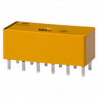
8. DIL terminal array
Deployed to fit a 2.54 mm
the terminals are presented in DIL arrays
which match the printed circuit board
terminal patterns commonly in
international use.
9. Relays that push the boundaries of
relay efficiency
High-density S relays take you close to
the limits of relay efficiency.
TYPICAL APPLICATIONS
Telecommunications equipment, data
processing equipment, facsimiles, alarm
equipment, measuring equipment.
Matsushita Electric Works, provides a
highly efficient polarized magnetic circuit
structure that is both highly sensitive and
has a small form factor. Moreover,
suitability for provision with many types of
contact array and other advantages
promise to make it possible to provide
many of the various characteristics that
are coming to be demanded of relays.
S RELAYS
Attraction
Repulsion
Residual plate
Permanent magnet
Repulsion
.100 inch
Axis
Attraction
grid,