G9EC-1-B DC24 Omron, G9EC-1-B DC24 Datasheet
G9EC-1-B DC24
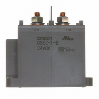
Specifications of G9EC-1-B DC24
G9EC-1-B-DC24
G9EC1B DC24
G9EC1BDC24
Z1619


Related parts for G9EC-1-B DC24


G9EC-1-B DC24 Summary of contents
Page 1
... Note: 1. Relays come with two M8 nuts for the main terminals (contacts). 2. Relays with coil terminals and screw terminals come with two M3.5 screws. Terminals Contact form Contact terminals Screw terminals SPST-NO DC Power Relays (200-A Models) Coil rated voltage Model 12 VDC G9EC-1-B 24 VDC G9EC-1 48 VDC 60 VDC 100 VDC G9EC-1 1 ...
Page 2
... A (15 min) 1,000 A at 400 VDC (10 times) 700 A at 400 VDC (40 times min.) –200 A at 200 VDC (1,000 times min.) –40 to 50°C (with no icing or condensation 85% Approx. 560 g G9EC-1 Maximum voltage Power voltage (See note 3.) consumption 110% of rated volt- Approx age G9EC-1(- ...
Page 3
... Engineering Data ■ G9EC-1(-B) Switching/Current Conduction Models Maximum Switching Capacity 1,000 500 300 100 DC resistive load 0.5 0.3 0 100 300 500 1,000 Switching voltage (V) Carry Current vs Energizing Time 100,000 10,000 1,000 100 10 100 300 500 700 1,000 Carry current (A) Electrical Endurance ...
Page 4
... Characteristics were measured after applying vibration at a frequency (single amplitude of 0.75 mm) to the test piece (not energized) for 2 hours each in 3 directions. The percentage rate of change is the average value for all of the samples Shock Resistance 5.0 Sample: G9EC-1 Number: 5 4.0 3.0 2.0 1.0 Must-operate voltage ...
Page 5
... VIEW) 1(+) 32 44 2(−) 7 Note: Be sure to connect terminals with the correct polarity. Coils do not have polarity. Mounting Hole Dimensions (TOP VIEW) Two 6.5-dia. holes 26.7 1(+) 86.7 68.6 (Coil terminal height) 10.5 32± 0.1 G9EC-1 8 86± 0.1 8 86± 0.1 5 ...
Page 6
... Options Terminal Cover P9EC Power Relays (200-A Models) 44 Dimensions of cutout for wiring G9EC-1 Note: Be sure to remove the cutouts for wiring that are located in the wiring outlet direction before in- stalling the Terminal Cover. Dimension Tolerance (mm) (mm) ±0 lower ±0 ± higher ...
Page 7
... M5 screws: 1.57 to 2.35 N·m • M4 screws: 0.98 to 1.37 N·m • M3.5 screws: 0.75 to 1.18 N·m 2. The G9EA and G9EC Relays’ contacts have polarity. Be sure to perform connections with the correct polarity. If the contacts are connected with the reverse polarity, the switching characteristics specified in this document cannot be assured ...
Page 8
... MEMO 8 DC Power Relays (200-A Models) G9EC-1 ...
Page 9
... Amendment: These Terms constitute the entire agreement between Buyer and Seller relating to the Products, and no provision may be changed or waived unless in writing signed by the parties. 5. Severability: If any provision hereof is rendered ineffective or invalid, such provision shall not invalidate any other provision. DC Power Relays (200-A Models) G9EC-1 9 ...
Page 10
... European Union's Directive on the Restriction of certain Hazardous Substances ("RoHS"), although the requirements of RoHS do not take effect until July 2006. These requirements may be subject to change. Please consult our website for current information. Specifications subject to change without notice G9EC-1 OMRON ON-LINE Global - http://www.omron.com USA - http://www.components.omron.com Printed in USA ...