G6B-1114P-1-US-DC24 Omron, G6B-1114P-1-US-DC24 Datasheet - Page 2
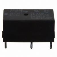
G6B-1114P-1-US-DC24
Manufacturer Part Number
G6B-1114P-1-US-DC24
Description
RELAY PCB MINI SPST 5A 24VDC
Manufacturer
Omron
Series
G6Br
Datasheet
1.G6B-1114P-US-DC12.pdf
(10 pages)
Specifications of G6B-1114P-1-US-DC24
Relay Type
General Purpose
Contact Form
SPST-NO (1 Form A)
Contact Rating (current)
5A
Switching Voltage
380VAC, 125VDC - Max
Coil Type
Standard
Coil Current
8.3mA
Coil Voltage
24VDC
Turn On Voltage (max)
16.8 VDC
Turn Off Voltage (min)
2.4 VDC
Mounting Type
Through Hole
Termination Style
PC Pin
Circuit
SPST-NO (1 Form A)
Contact Rating @ Voltage
5A @ 250VAC
Control On Voltage (max)
16.8 VDC
Control Off Voltage (min)
2.4 VDC
Coil Voltage Vdc Nom
24V
Contact Current Max
5A
Contact Voltage Ac Nom
250V
Contact Voltage Dc Nom
30V
Coil Resistance
2880ohm
Contact Configuration
SPST-NO
Contact Rating
5 A at 250 VDC / 30VAC, 8 A at 250 VAC / 30 VDC
Contact Termination
PCB
Mounting Style
PCB
Power Consumption
200 mW
Contact Material
Silver Alloy
Lead Free Status / RoHS Status
Lead free / RoHS Compliant
Lead Free Status / RoHS Status
Lead free / RoHS Compliant, Lead free / RoHS Compliant
Other names
G6B-1114P-1USDC24
G6B-1114P-1USDC24
G6B1114P1USDC24
Z2850
G6B-1114P-1USDC24
G6B1114P1USDC24
Z2850
Available stocks
Company
Part Number
Manufacturer
Quantity
Price
Company:

Part Number:
G6B-1114P-1-US-DC24V
Manufacturer:
OMRON
Quantity:
12 000


■ Accessories (Order Separately)
Back Connecting Sockets
Note: 1. Not applicable to the self-clinching type.
Specifications
■ Contact Ratings
Note: P level:
■ Coil Ratings
Non-latching, Single Pole
Note: 1. The rated current and coil resistance are measured at a coil temperature of 23°C with a tolerance of ±10%.
150
G6B(U)-1114P-US-P6B
G6BK-1114P-US-P6B
G6B-2@@4P-US-P6B
G6B-1174P-US-P6B
Removal Tool
Hold-down Clips
Load
Rated load
Contact material
Rated carry current
Max. switching voltage
Max. switching current
Max. switching capacity
Min. permissible load
(reference value - see note)
Load
Rated load
Contact material
Rated carry current
Max. switching voltage
Max. switching current
Max. switching capacity
Min. permissible load
(reference value - see note)
5
6
12
24
voltage
Rated
(VDC)
2. Use the G6B-@@@@P-US-P6B if mounting relays in a P6B Socket.
2. Operating characteristics are measured at a coil temperature of 23°C.
Applicable Relay
λ
Power PCB Relay
Item
Item
60
40
33.30
16.70
8.30
= 0.1 x 10
current
Rated
(mA)
-6
/operation
125
180
720
2,880
resistance
Resistive load
(cosφ = 1)
5 A at 250 VAC;
5A at 30 VDC
Ag Alloy (Cd free)
5 A
380 VAC, 125 VDC
5 A
1,250 VA, 150 W
10 mA at 5 VDC
Resistive load (cosφ = 1)
8 A at 250 VAC; 8 A at 30 VDC
Ag Alloy (Cd free)
8 A
380 VAC, 125 VDC
8 A
2,000 VA, 150 W
10 mA at 5 VDC
Coil
(Ω)
G6B
P6B-04P
P6B-06P
P6B-26P
P6B-04P
P6B-Y1
P6B-C2
Back Connecting Socket (See note 1.)
0.28
0.31
1.2
4.9
Armature
OFF
Coil inductance
(ref. value)(H)
SPST-NO
Inductive load
(cosφ = 0.4; L/R = 7 ms)
2 A at 250 VAC;
2 A at 30 VDC
500 VA, 60 W
0.26
0.28
1.1
4.1
Armature
ON
SPST-NO (High-capacity)
70% max.
Pick-up
voltage
Inductive load (cosφ = 0.4; L/R = 7 ms)
2 A at 250 VAC; 2 A at 30 VDC
Resistive load
(cosφ = 1)
5 A at 250 VAC;
5A at 30 VDC
1,250 VA, 150 W
% of rated voltage
SPST-NO + SPST-NC, DPST-NO, DPST-NC
10% min.
Dropout
voltage
160% max. @
23°C
Inductive load
(cosφ = 0.4; L/R = 7 ms)
1.5 A at 250 VAC;
1.5 A at 30 VDC
375 VA, 80 W
voltage
Max.
Approx. 200
consumption
Power
(mW)
Related parts for G6B-1114P-1-US-DC24
Image
Part Number
Description
Manufacturer
Datasheet
Request
R

Part Number:
Description:
Power PCB Relay
Manufacturer:
Omron
Datasheet:
Part Number:
Description:
POWER PCB RELAY
Manufacturer:
Omron
Datasheet:
Part Number:
Description:
POWER PCB RELAY
Manufacturer:
Omron
Datasheet:
Part Number:
Description:
Power PCB Relay
Manufacturer:
Omron
Datasheet:
Part Number:
Description:
POWER PCB RELAY
Manufacturer:
Omron
Datasheet:
Part Number:
Description:
POWER PCB RELAY
Manufacturer:
Omron
Datasheet:
Part Number:
Description:
Power PCB Relay
Manufacturer:
Omron
Datasheet:

Part Number:
Description:
RELAY PC MNT SPST-NO 5A 12VDC
Manufacturer:
Omron
Datasheet:
Part Number:
Description:
RELAY PC MNT SPST-NO 5A 6VDC
Manufacturer:
Omron
Datasheet:
Part Number:
Description:
RELAY PC MNT 5A SPST-NO 5VDC
Manufacturer:
Omron
Datasheet:
Part Number:
Description:
RELAY PC MNT SPST-NO 5A 24VDC
Manufacturer:
Omron
Datasheet:

Part Number:
Description:
RELAY PWR SPST-NO PCB 12VDC
Manufacturer:
Omron
Datasheet:
Part Number:
Description:
POWER PCB RELAY
Manufacturer:
Omron
Datasheet:
Part Number:
Description:
POWER PCB RELAY
Manufacturer:
Omron
Datasheet:
Part Number:
Description:
POWER PCB RELAY
Manufacturer:
Omron
Datasheet: