G7J-4A-B DC24 Omron, G7J-4A-B DC24 Datasheet - Page 6
G7J-4A-B DC24
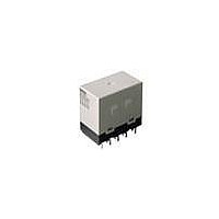
Manufacturer Part Number
G7J-4A-B DC24
Description
RELAY PWR 4PST 25A 24VDC
Manufacturer
Omron
Series
G7Jr
Datasheet
1.R99-04_FOR_G5F.pdf
(8 pages)
Specifications of G7J-4A-B DC24
Relay Type
General Purpose
Contact Form
4PST (4 Form A)
Contact Rating (current)
25A
Switching Voltage
250VAC, 125VDC - Max
Coil Type
Standard
Coil Current
83mA
Coil Voltage
24VDC
Turn On Voltage (max)
18 VDC
Turn Off Voltage (min)
2.4 VDC
Mounting Type
Chassis Mount
Termination Style
Screw Terminal
Circuit
4PST (4 Form A)
Contact Rating @ Voltage
25A @ 220VAC
Control On Voltage (max)
18 VDC
Control Off Voltage (min)
2.4 VDC
Contact Rating
25 A at 220 VAC / 30 VDC
Contact Termination
Screw
Power Consumption
2 W
Lead Free Status / RoHS Status
Lead free / RoHS Compliant
Other names
G7J-4A-B-DC24
G7J4ABDC24
G7J4ABDC24


Reference
UL approval:
CSA approval: CSA C22.2 No. 14 for industrial control devices
VDE - EN60255-1-00: 1997 and EN60255-23: 1996(File No. 5381UG)
Note: Add the suffix “-KM” to the model number when ordering.
KEMA - EN60947-4-1 and IEC947-4-1 for contacts (File No. 2001291.02)
Note: Add the suffix “-KM” to the model number when ordering. *This rating is the bifurcated contact rating.
Precautions
Note: Be sure to read the precautions and information common to all relays, contained in the Technical User’s Guide,
■ Correct Use
Installation
PCB Terminal-equipped Relays weigh approximately 140 g. Be sure that
the PCB is strong enough to support them. We recommend dual-side
through-hole PCBs to reduce solder cracking from heat stress.
Mount the G7J with its test button facing downwards. The Relay may
malfunction due to shock if the test button faces upwards. Be careful
not to press the test button by mistake because the contacts will go
ON if the test button is pressed.
Be sure to use the test button for test purposes only.
The test button is used for Relay circuit tests, such as a circuit conti-
nuity test. Do not attempt to switch the load with the test button. If a
voltage is applied to the coil, the test button will retract in an ON state
(i.e., an excited state).
Micro Loads
The G7J is used for switching power loads, such as motor, trans-
former, solenoid, lamp, and heater loads. Do not use the G7J for
switching minute loads, such as signals. Use a Relay with a bifur-
cated contact construction for switching micro loads, in which case,
however, only SPST-NO or SPST-NC output is obtained.
Soldering PCB Terminals
Be sure to solder the PCB terminals manually only. In the case of
automatic soldering, some flux may stick to the test button and the
G7J. As a result, the G7J may malfunction.
The G7J is not of enclosed construction. Therefore, do not wash the
G7J with water or any detergent.
Connecting
Refer to the following diagram when connecting a wire with a screw
terminal to the G7J.
304
G7J-4A-B(P) (T)
G7J-2A2B(P) (T)
G7J-3A1B-B(P) (T)
G7J-4A-B(P) (T) (Z)
G7J-2A2B(P) (T)
G7J-3A1B-B(P) (T) (Z)
“Electromechanical Relays - Technical Information”, for correct use.
Model
General Purpose Relay
UL508 for industrial control devices
UL1950 for information processing equipment including business machines
CSA C22.2 No. 950 for information processing equipment including business machines
4.5
7
Model
6, 12, 24, 48, 100 VDC
24, 50, 100 to 120, 200 to 240 VAC
7.6
M3.5
Coil ratings
G7J
8.8
200 to 240 VAC
6, 12, 24, 48, 100 VDC
24, 50, 100 to 120, 200 to 240 VAC
Coil ratings
25 A 240 VAC cosφ = 0.4
25 A 240 VAC cosφ = 1
25 A 30 VDC L/R ≥ 1
Allow suitable slack on leads when wiring, and do not subject the ter-
minals to excessive force.
Tightening torque: 0.98 N·m
Do not impose excessive external force on the G7J in the horizontal
or vertical directions when inserting the G7J to the Faston receptacle
or pulling the G7J out from the Faston receptacle. Do not attempt to
insert or pull out more than one G7J Unit together.
Do not solder the tab terminals.
Operating Coil
Internal Connections of Coils
If a transistor drives the G7J, check the leakage current, and connect
a bleeder resistor if necessary.
The AC coil is provided with a built-in full-wave rectifier that prevens
contact chatter during a voltage drop. This circuit allows the relays to
withstand, with no vibration or shock, voltage drops to the coil of up
to 50% of the rated coil voltage for 1 second max.
If a triac, such as an SSR, drives the AC coil of the G7J, the G7J may
not release. Be sure to perform a trial operation with the G7J and the
triac before applying them to actual use.
NO contact
A2
A2
Class AC1: 25 A at 220 VAC
11.5 A at 380 to 480 VAC
Class AC3: 11.5 A at 220 VAC and 8.5 A at 380
to 480 VAC
*Class AC1: 1 A at 220 VAC
Contact ratings
Contact ratings - NO contact
DC coil
AC coil
8 A 240 VAC cosφ = 0.4
8 A 240 VAC cosφ = 1
8 A 30 VDC L/R ≥ 1
NC contact
A1
A1
Related parts for G7J-4A-B DC24
Image
Part Number
Description
Manufacturer
Datasheet
Request
R

Part Number:
Description:
RELAY PWR 4PST 25A 120VAC
Manufacturer:
Omron
Datasheet:
Part Number:
Description:
RELAY PWR 4PST 25A 240VAC
Manufacturer:
Omron
Datasheet:

Part Number:
Description:
General Purpose Relay
Manufacturer:
Omron
Datasheet:
Part Number:
Description:
General Purpose Relay
Manufacturer:
Omron
Datasheet:
Part Number:
Description:
RELAY PWR 4PST 25A 24VDC
Manufacturer:
Omron
Datasheet:
Part Number:
Description:
RELAY
Manufacturer:
Omron
Datasheet:

Part Number:
Description:
RELAY
Manufacturer:
Omron
Datasheet:
Part Number:
Description:
RELAY (VDE)
Manufacturer:
Omron
Datasheet:
Part Number:
Description:
GENERAL PURPOSE RELAY
Manufacturer:
Omron
Datasheet:

Part Number:
Description:
RELAY, 4PNO, 24VDC
Manufacturer:
Omron
Datasheet:

Part Number:
Description:
RELAY
Manufacturer:
Omron
Datasheet:
Part Number:
Description:
RELAY
Manufacturer:
Omron
Datasheet:
Part Number:
Description:
RELAY
Manufacturer:
Omron
Datasheet: