SPECIFICATIONS
Contact
** Holding voltage should be 60% V of nominal voltage
Coil
#1 This value can change due to the switching frequency, environmental conditions,
Remarks
*
*
*
Types
Arrangement
Initial contact resistance, max.
(By voltage drop 6 V DC 1 A)
Contact material
Rating
(resistive
load)
Expected
life (min.
ope.)
Nominal operating power
1
2
3
Detection current: 10mA
Excluding contact bounce time
Half-wave pulse of sine wave: 11ms; detection time: 10µs
and desired reliability level, therefore it is recommended to check this with the
actual load.
Nominal switching
capacity
Max. switching power
Max. switching voltage
Max. switching current
Min. switching
capacity
Mechanical
(at 180 cpm)
Electrical at 10 A
125 V AC,
6 A 277 V AC resistive
(standard)
10 A 277 V AC
resistive (High power)
10 A 250 V AC
resistive
(Standard: at 20 cpm)
(High power: at 20
cpm, 105°C 221°F)**
.866
22
#1
16
.630
16
.630
10 A 250 V AC
10 A 125 V AC
mm
Standard type
6 A 277 V AC
(No contact
1 Form A,
1 Form C
5 × 10
inch
only)
10
250 V AC, 100 V DC
10 A (AC), 5 A (DC)
100 mA, 5 V DC
5
AgSnO
4
2,500 VA
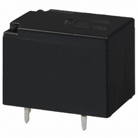
MINIATURE PC BOARD TYPE
360 mW
100 mΩ
FEATURES
• Miniature size with universal terminal
• High contact capacity: 10 A
• Class B coil insulation type available
• TV-5 type available (Standard type)
• VDE, TÜV also approved
• Sealed construction for automatic
10
footprint
1 Form A type → TV-5
1 Form C type → TV-5 (N.O. side only)
cleaning (Standard type)
High power type
2
7
10 A 250 V AC
10 A 125 V AC
10 A 277 V AC
type
1 Form A
1.5 × 10
2×10
POWER RELAY
5
5
Characteristics
*
*
*
*
Max. operating speed
Types
Initial insulation resistance
Initial
breakdown
voltage*
Operate time*
(at nominal voltage)
Release time(without diode)*
voltage)
Temperature rise (at nominal voltage)
Shock resistance
Vibration resistance
Conditions for operation,
transport and storage*
(Not freezing and
condensing at low
temperature)
Unit weight
4
5
6
7
Half-wave pulse of sine wave: 6ms
Detection time: 10µs
Refer to 6. Conditions for operation, transport and storage mentioned in
AMBIENT ENVIRONMENT.
When using relays in a high ambient temperature, consider the pick-up voltage
rise due to the high temperature (a rise of approx. 0.4% V for each 1°C
with 20°C
maximum allowable voltage range.
1
68°F
2
as a reference) and use a coil impressed voltage that is within the
Between open contacts
Between contacts and
coil
6
COMMENTS ABOUT Cd
FREE
We have introduced Cadmium free type
products to reduce the material which is
not good for our environment. (The suffix
“F” should be added to the part number.)
If you are still using Cadmium containing
parts, which don’t have “F” on the suffix
of the part number, please use Cadmium
free parts from now on. The life of the
Cadmium free parts may be shorter than
the Cadmium containing parts based on
the load condition, so please evaluate the
Cadmium free parts with your actual
application before use.
Functional*
Destructive*
Functional*
Destructive
Ambient
temp.*
Humidity
JS RELAYS
2
(at nominal
7
3
5
4
Min. 100 MΩ (at 500 V DC)
Approx. 117.6 m/s
resistive, nominal voltage
Contact carrying current:
Standard
Approx. 98 m/s
–40°C to
–40°F to
Min. 980 m/s
+185°F
1,500 Vrms for 1 min.
10 to 55 Hz at double
10 to 55 Hz at double
+85°C
amplitude of 1.6 mm
Approx.12 g
750 Vrms for 1 min.
10A, at 85°C
Min. 98 m/s
type
amplitude of 2 mm
applied to coil.
5 to 85% R.H.
Max. 10 ms
Max. 10 ms
Max. 35°C,
20 cpm
VDE
High power
2
2
.423 oz
–40°C to
–40°F to
{10 G}
{100 G}
2
+105°C
+221°F
185°F
{10 G},
2
type
{12 G},
33.8°F
JS


