AGQ200A03Z Panasonic Electric Works, AGQ200A03Z Datasheet - Page 5
AGQ200A03Z
Manufacturer Part Number
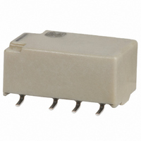
AGQ200A03Z
Description
RELAY DPDT 1A POLAR 3VDC SMD
Manufacturer
Panasonic Electric Works
Series
AGQr
Type
General Purpose Relayr
Datasheet
1.AGQ200A03Z.pdf
(5 pages)
Specifications of AGQ200A03Z
Relay Type
Telecom
Circuit
DPDT (2 Form C)
Contact Rating @ Voltage
1A @ 30VDC
Coil Type
Standard
Coil Current
46.7mA
Coil Voltage
3VDC
Control On Voltage (max)
2.25 VDC
Control Off Voltage (min)
0.3 VDC
Mounting Type
Surface Mount
Termination Style
Gull Wing
Relay Construction
Non-Latching
Contact Arrangement
DPDT
Coil Voltage Dc
3V
Contact Form
2 Form C
Voltage Rating (vdc)
110V
Voltage Rating (vac)
125V
Dropout Volt (min)
0.3VDCV
Coil Resistance
64.2Ohm
Pick-up Voltage (max)
2.25VDC
Maximum Power Rating
30W/37.5VA
Operate Time
4ms
Contact Current Rating
1A
Contact Material
AgPd
Coil Suppression Diode
No
Push To Test Button
No
Led Indicator
No
Seal
Sealed
Product Height (mm)
5.4mm
Product Depth (mm)
7.2mm
Product Length (mm)
10.6mm
Operating Temp Range
-40C to 85C
Pin Count
8
Mounting Style
Surface Mount
Lead Free Status / RoHS Status
Lead free / RoHS Compliant
Other names
255-2091-2
AGQ200A03Z
AGQ200A03Z
Available stocks
Company
Part Number
Manufacturer
Quantity
Price
Company:

Part Number:
AGQ200A03Z
Manufacturer:
Panasonic Electric Works
Quantity:
1 800
Company:
Part Number:
AGQ200A03Z
Manufacturer:
Panasonic
Quantity:
12 000
Part Number:
AGQ200A03Z
Manufacturer:
PANASONIC/松下
Quantity:
20 000


2. Surface-mount terminal
Schematic (Top view)
NOTES
1. Packing style
1) The relay is packed in a tube with the
relay orientation mark on the left side, as
shown in the figure below.
2) Tape and reel packing
(A type)
(1)-1 Tape dimensions
High sensitivity single side stable
CAD Data
GQ relays
Stopper (green)
Stopper (green)
A type
S type
Relay polarity bar
(Z type)
Type
(Deenergized condition)
Single side stable
Orientation (indicates PIN No.1) stripe
Orientation (indicates PIN No.1) stripe
Direction indication
Tape coming out direction
8
1
General tolerance 0.1 mm
1.50
.059
7
2
Single side stable/1 coil latching/High sensitivity single side stable
12.0
.472
6
3
+0.1
+.003
0
.0
.079
Max. 5.40
Max. 5.40
.016 .004
.016 .004
5
4
2.0
dia.
dia.
0.40 0.1
0.40 0.1
3.20 0.15
.126 .006
3.20 0.15
.126 .006
.213
.213
.354
9.0
4.00
.157
2.00 dia.
.079 dia.
10.60 0.3
.417 .012
10.60 0.3
.417 .012
1.75
.069
11.5
.453
11.1
.437
.004 inch
Stopper (red)
Stopper (red)
24.0 0.3
.945 .012
2.20 0.15
.087 .006
2.20 0.15
.087 .006
Max. 6.55
External dimensions
2.20 0.15
.087 .006
2.20 0.15
.087 .006
All Rights Reserved © COPYRIGHT Panasonic Electric Works Co., Ltd.
mm
0.40
.016
.256
inch
.008 .004
0.20 0.1
(Reset condition)
Direction indication
1 coil latcing
(S type)
(1)-2 Tape dimensions
(2) Dimensions of plastic peel
8
1
GQ relays
Relay polarity bar
(Z type)
7.20 0.3
.283 .012
7.20 0.3
.283 .012
7.20 0.3
.283 .012
7
2
6
3
5
4
.079
0.20 0.1
.008 .004
5.08 0.15
.200 .006
2.0
5.08 0.15
.200 .006
Tape coming out direction
8.40 0.3
.331 .012
General tolerance 0.1 mm
1.50
.059
12.0
.472
+0.1
+.003
0
.0
.079
2.0
dia.
dia.
21 dia.
.827 dia.
13 dia.
.512 dia.
.307
7.8
4.0
.157
2.00 dia.
.079 dia.
1.75
.069
11.1
.437
11.5
.453
.004 inch
.945 .012
Single side stable/1 coil latching/High sensitivity single side stable
24.0 0.3
80 1 dia.
3.150 .039 dia.
330 2 dia.
12.992 .079 dia.
Max. 6.55
mm
.256
Suggested mounting pad (Tolerance: 0.1 .004)
inch
0.40
.016
2. Automatic insertion
To maintain the internal function of the
relay, the chucking pressure should not
exceed the values below.
Chucking pressure in the direction A :
9.8 N {1 kgf} or less
Chucking pressure in the direction B :
9.8 N {1 kgf} or less
Chucking pressure in the direction C :
9.8 N {1 kgf} or less
Please chuck the
Avoid chucking the center of the relay.
In addition, excessive chucking pressure
to the pinpoint of the relay should be also
avoided.
3.20
.126
3.20
.126
For general cautions for use,
please refer to the “Cautions for
use of Signal Relays” or “General
Application Guidelines”.
0.80
.031
0.80
.031
2.20
.087
2.20
.087
2.20
.087
2.20
.087
2.66 6.74
.105 .265
2.06
.081
A
6.14
.242
C
GQ (AGQ)
portion.
B
Related parts for AGQ200A03Z
Image
Part Number
Description
Manufacturer
Datasheet
Request
R

Part Number:
Description:
Manufacturer:
Panasonic Electric Works
Datasheet:
Part Number:
Description:
Manufacturer:
Panasonic Electric Works
Datasheet:

Part Number:
Description:
CONN SOCKET P4 .4MM 50POS SMD
Manufacturer:
Panasonic Electric Works
Datasheet:
Part Number:
Description:
CONN SOCKET .8MM 16POS SMD
Manufacturer:
Panasonic Electric Works
Datasheet:
Part Number:
Description:
CONN HEADER .8MM 16POS SMD
Manufacturer:
Panasonic Electric Works
Datasheet:
Part Number:
Description:
CONN SOCKET .8MM 20POS SMD
Manufacturer:
Panasonic Electric Works
Datasheet:
Part Number:
Description:
CONN SOCKET .8MM 20POS SMD
Manufacturer:
Panasonic Electric Works
Datasheet:
Part Number:
Description:
CONN HEADER .8MM 20POS SMD
Manufacturer:
Panasonic Electric Works
Datasheet:
Part Number:
Description:
CONN SOCKET .8MM 22POS SMD
Manufacturer:
Panasonic Electric Works
Datasheet:
Part Number:
Description:
CONN SOCKET .8MM 30POS SMD
Manufacturer:
Panasonic Electric Works
Datasheet:
Part Number:
Description:
CONN HEADER .8MM 30POS SMD
Manufacturer:
Panasonic Electric Works
Datasheet:
Part Number:
Description:
CONN SOCKET .8MM 30POS SMD
Manufacturer:
Panasonic Electric Works
Datasheet:
Part Number:
Description:
CONN SOCKET .8MM 30POS SMD
Manufacturer:
Panasonic Electric Works
Datasheet:
Part Number:
Description:
CONN HEADER .8MM 30POS SMD
Manufacturer:
Panasonic Electric Works
Datasheet:
Part Number:
Description:
CONN HEADER BRD/BRD .5MM 60POS
Manufacturer:
Panasonic Electric Works
Datasheet: