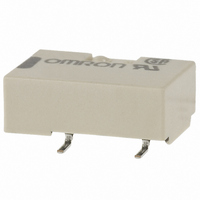
G6L-1F-DC24 Omron, G6L-1F-DC24 Datasheet - Page 3

G6L-1F-DC24
Manufacturer Part Number
G6L-1F-DC24
Description
RELAY TELCOM SPST 24V SMD
Manufacturer
Omron
Series
G6Lr
Datasheet
1.G6L-1F_DC12.pdf
(10 pages)
Specifications of G6L-1F-DC24
Relay Type
Telecom
Circuit
SPST-NO (1 Form A)
Contact Rating @ Voltage
1A @ 24VDC
Coil Type
Standard
Coil Current
9.6mA
Coil Voltage
24VDC
Control On Voltage (max)
18 VDC
Control Off Voltage (min)
2.4 VDC
Mounting Type
Surface Mount
Termination Style
Gull Wing
Contact Form
1 Form C
Power Consumption
230 mW
Contact Rating
0.3 A at 125 VAC, 1 A at 24 VDC
Lead Free Status / RoHS Status
Lead free / RoHS Compliant
Lead Free Status / RoHS Status
Lead free / RoHS Compliant, Lead free / RoHS Compliant
Other names
G6L1FDC24
Z2040
Z2040
Available stocks
Company
Part Number
Manufacturer
Quantity
Price
Company:
Part Number:
G6L-1F-DC24V
Manufacturer:
OMRON
Quantity:
12 000
Engineering Data
Maximum Switching Capacity
Electrical Service Life
Electrical Service Life (with Must
Operate and Must Release
Voltage) (See note 1)
Note:
100
1,000
0.7
0.5
0.3
0.1
500
300
100
80
60
40
20
10
50
30
10
0
7
5
3
1
10
5
3
1
0.1
0
Sample: G6L-1F
Number of Relays: 10
Test conditions: 1-A resistive load at
24-VDC with an operation rate of 50%
Switching frequency: 1,800 operations/h
1.
2.
DC resistive load
125-VAC resistive load
Must operate voltage
Must release voltage
The tests were conducted at an ambient temperature of 23°C.
The contact resistance data are periodically measured reference values and are not values from each monitoring operation. Contact resistance values will vary according
to the switching frequency and operating environment, so be sure to check operation under the actual operating conditions before use.
Operating frequency (×10
0.2
30
1
0.4
50 70 100
AC resistive load
10
0.6
Switching voltage (V)
24-VDC resistive load
Switching current (A)
0.8
300 500 7001,000
3
100
operations)
max.
min.
max.
min.
1
1,000
1.2
Ambient Temperature vs.
Ambient Temperature vs. Must
Operate or Must Release Voltage
Electrical Service Life
(Contact Resistance) (See note 1)
Note:
Maximum Voltage
100
1,000
250
200
150
100
90
80
70
60
50
40
30
20
10
50
−60
500
300
100
0
−40
0
50
30
10
“Maximum Voltage” is the maximum voltage that can
be applied to the relay coil.
0.1
Contact resistance
Sample: G6L-1F
Number of Relays: 10
Test conditions: 1-A resistive load at
24-VDC with an operation rate of 50%
Switching frequency: 1,800 operations/h
−40
−20
Operating frequency (×10
24 VDC
−20
1
0
3 to 12 VDC
0
Ambient temperature (˚C)
Ambient temperature (˚C)
20
10
20
Max. estimated value
Must operate voltage
Must release voltage
40
40
100
3
operations)
max.
min.
NO contact
60
60
max.
avg.
min.
max.
avg.
min.
1,000
80
80
Ambient Temperature vs.
Shock Malfunction
Contact Reliability Test (Contact
Resistance) (See notes 1 and 2)
Switching Current
Shock direction
Conditions: Shock is applied in ±X, ±Y, and ±Z
directions three times each with and without energizing
the Relays to check the number of contact
malfunctions.
1,000
Y
Y'
X
1.2
0.8
0.6
0.4
0.2
1,000
1,000
500
300
100
50
30
10
1
0
−40
Z'
X
Low Signal Relay
1
Sample: G6L-1F
Number of Relays: 10
Test conditions: 1-A resistive load at
24-VDC with an operation rate of 50%
Switching frequency: 1,800 operations/h
X'
Z
Z'
−20
Operating frequency (×10
10
1,000
200
400
600
800
0
Y
Y'
1,000
800
600
400
200
Ambient temperature (˚C)
20
100
Unit: m/s
Sample: G6L-1F
Number of Relays: 10
Energized
G6L
40
2
1,000
3
operations)
1,000
1,000
NO contact
Z
X'
60
10,000
max.
min.
80
39


