8008170000 Weidmuller, 8008170000 Datasheet
8008170000
Specifications of 8008170000


Related parts for 8008170000


8008170000 Summary of contents
Page 1
Relay Coupler 58 ...
Page 2
Relay Coupler The universal foot of the Weidmüller relay modules allow them to be assembled 7.5 and mounting rails in accordance with European standards EN 50 035 and EN 50 ...
Page 3
... Relay couplers with plugged relays Relay couplers with plugged relays are only conditionally suitable for use in appli- cations subject to heavy vibrations. Relay couplers with soldered relays are to be preferred. Derating curves The contact resistance is largely responsi- ble for heat development within the relay. ...
Page 4
... EN 50 178 or DIN VDE 0106 Part 101. As more and more users employ only equipment that guarantees "protec- tive separation", a lot of manufacturers of relays refer to DIN VDE 0106 and test their products accordingly. Consequently, the quoted values correspond to the require- ments for "protective separation". ...
Page 5
... EG 7 relay couplers can be optionally mounted onto rails. The RST EG 7 locking socket is also avail- able for use with the pluggable relays cou- plers. The enclosed EG 7 housing are equipped with clamping yoke screw connections. The following conductor cross-sections can be connected: NO/NC: 0 ...
Page 6
... Types of Housings for Relay Coupler Weidmüller RS locking socket Locking sockets with relays RS 30, 31, 32 are either 11 wide depending on version. The open profile makes the use of pluggable relays possible. Modules mounted onto the locking sock- ets are provided with clamping yoke screw connections or push-on connectors for wiring conductors ...
Page 7
... Page 80 PLUGSERIES PRS / PRZ RS 30 1101661001 1101611001 1101621001 1101761001 1101711001 1101721001 Page RSM DKR 32 8016620000 8008110000 Page 70 DKR 35 8016610000 8008170000 Page 70 8215620000 Page 71 DKR 35/32 MCZ R MICROSERIES MRS / MRZ * Approval by Germanischer Lloyd Reliable separation 0133560000 Page 72 0542660000 Page 72 8275350000 8418240000 8418270000 ...
Page 8
Relay Coupler Electromechanical switching Output 48 V Housing EG 0662660000 0662460000 Page 72 Page 72 WAVESERIES WRS EG 7* 8092370000 8092380000 Page 81 Page 1101861001 1101161001 1101811001 1101111001 1101821001 1101121001 1101961001 1101261001 1101911001 1101211001 1101921001 1101221001 Page ...
Page 9
Relay Coupler Electromechanical switching Output 230 V Housing EG 0543860000 Page 72 WAVESERIES WRS EG 7* 8092460000 8178200000 Page 81 PLUGSERIES PRS / PRZ RS 30 1102261001 1102211001 1102221001 Page RSM MCZ R MICROSERIES MRS ...
Page 10
Relay Coupler Electromechanical switching Output 12 V Housing EG WAVESERIES WRS EG 7* 8092310000 8092320000 Page 80 Page 80 PLUGSERIES PRS / PRZ RS 30 1129421001 1129521001 Page 91 Page DKR 35 8171100000 Page 70 MICROSERIES MRS ...
Page 11
Relay Couplers in Component Housings Miniconditioners MCZ R Schematic circuit diagram This module can be used as a universal inter- face between the controller and actuator for switching medium-sized loads. Reduces installation and commissioning times by use of the proven ...
Page 12
Relay Couplers in Component Housings MCZ R 110 Vdc MCZ R 120 Vac Limit diagram U/Vdc 300 prohibited area 200 100 Type Cat. No. Type Cat. No. MCZ R 110 Vdc 8467470000 MCZ ...
Page 13
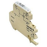
... Cat. No. Type Cat. No. 0687560000 AP DKT4 0687560000 Page 305 DKR 24 Vdc Type Cat. No. DKR 24 Vdc 8016620000 DKR 24 Vdc 8008170000 Input: bottom 24 Vdc ±20 % 9.3 mA 225 mW typ. 0.7…2.5 ms typ. 0.2…2.0 ms 500 mA 10 W/10 VA 100 V 500 RH/RU 1 normally-open contact 9 10 ...
Page 14
Relay Couplers in Component Housings Mini coupler DKR DKR 24 Vac/dc DK5R-1U Type Cat. No. Type Cat. No. DKR 24 Vdc 8215620000 DK5R-1U 9454910000 Input: top Input: bottom 24 Vdc ± Vac/dc ± mAac/7 ...
Page 15
Relay Coupler in Component Housings EG 2 with Schematic circuit diagram Ordering data Rated data Input voltage Rated consumption – (W) Rated consumption ~ (VA) Drop-out current of the relay** (at 20 °C) Max. output ...
Page 16
Relay Coupler in Component Housings EG 2 with 2.8-mm tab connection Schematic circuit diagram Ordering data Rated data Input voltage Rated consumption – (W) Rated consumption ~ (VA) Drop-out current of the relay** (at 20 °C) Max. output voltage Continuous ...
Page 17
WAVESERIES Relay Coupler in Component Housings With 1 changeover contact Relay couplers in the WAVEBOX Independent connection technology - pluggable connection unit screw or tension clamp technology Fast commissioning and after-sales- service service - pluggable PCBs Save wiring tasks - ...
Page 18
WAVESERIES Relay Coupler in Component Housings WRS 1 24/115 VUC WRS 1 24 VUC 230 VAC Type Cat. No. Type Cat. No. WRS 1 24/115 Vuc WRS 1 24 Vuc/230 Vac 8418220000 8418230000 WRZ 1 8430210000 WRZ 1 8430220000 24 ...
Page 19
WAVESERIES Relay Coupler in Component Housings with 2 NO contacts Mounted horizontally WRS 2 12/24 VDC -> 8418240000 waagerecht montiert Control 26.4 Vdc 26.4 Vdc Ansteuerung 26,4Vdc 8 clearance ≥ Abstand>=10mm mounted angereiht ...
Page 20
WAVESERIES Relay Coupler in Component Housings with 1NC / 1 NO Mounted horizontally Control 26.4 Vdc 26.4 Vdc 8 7 Abstand>=10mm clearance ≥ mounted angereiht Ambient ...
Page 21
WAVESERIES Relay Coupler in Component Housings with 2 changeover contacts WRS 2 12/24 VDC 8418300000 Mounted horizontally waagerecht montiert Ansteuerung 26,4Vdc Control 26.4 Vdc 26.4 Vdc 7 clearance ≥ Abstand>=10mm angereiht mounted ...
Page 22
WAVESERIES Relay Coupler in Component Housings with 3 NO contacts WRS 2 24 VUC 8418330000 Mounted horizontally waagerecht montiert; Ansteurung 26,4Vdc Control 26.4 Vdc 26.4 Vdc 7 6 Abstand>=10mm clearance ≥ angereiht mounted ...
Page 23
... Continuous current Ambient temperature Ordering data Combination foot for TS 15 EGR EG 7 spare relays, without connection unit Plug-in relay-coupl., without engagem. socket, 1 changeo. cont. Engage.socket f. plug-in relay coupler w. combin.foot TS 32, 35 Rated data of the coil Input voltage Rated consumption Max ...
Page 24
Relay Couplers in Components Housings EG 7 EGR Type Cat. No. Type Cat. No. EGR EG7 8092370000 EGR EG7 8092400000 EGR EG7 8092380000 EGR EG7 8092410000 1) EGR EG7 8092390000 EGR EG7 8092420000 RST ...
Page 25
... Relay socket for mounting rails - LED indicator unit / RC combination - retainer clip - pluggable relays Independent connection technology: screw or tension clamp technology Compatible with low power relays type RT / Standard with contacts Coil and root-contacts cross-con- nectable with cross-connection type ZQV 2.5 N Available as complete module or as ...
Page 26
... PLUGSERIES Relays on Sockets Accessories 87 (PXZ35) 95 (PXS35) Screw Tension connection clamp 15,3 15.3 15 (NC) (NC (COM) (COM (NO) (NO (COIL) (COIL) Operating indication DC-Version free wheel diode AC-Version marking field retaining-clip 87 Cross-connections channel Empty base for rail mounted TS 35 Screw connection Tension clamp connection ...
Page 27
... PLUGSERIES Relays on Sockets Pluggable relay types Print figure/circuit diagram Relay type RT/SGR 84 1 changeover contact 2 changeover contacts Pluggable relay 12 Vdc 1 changeover contact 12 Vdc 2 changeover contacts 24 Vdc 1 changeover contact 24 Vdc 1 changeover contact AU 24 Vdc 2 changeover contacts 24 Vdc 2 changeover contacts AU 48 Vdc 1 changeover contact ...
Page 28
... Vac 4 kVA 10 mA /100 mW 500 typ. 10/3 ms typ. 0.5 > switching operations -25°C ... +70° SEV, UL, CSA, DEMKO, VDE, PTB RP 3SL Relays for high switching currents Type Schrack RP 3SL Cat. No RP3SL 24 Vdc 1NO 8588510000 1 normally-open contact AgSnO 120 250 V 4 kVA 500 typ ...
Page 29
Relay Couplers on Sockets MICROSERIES in Terminal Format MICRO RELAY MRS/MRZ This module can be used as a universal interface between the controller and actuator for switching small to medium-sized loads. Pluggable cross-connection in the input and output reduces wiring ...
Page 30
Relay Couplers on Sockets MICROSERIES in Terminal Format MRS 24 Vdc 1CO MRS 24 Vuc 1CO MRZ 24 Vdc 1CO MRZ 24 Vuc 1CO Type Cat. No. Type Cat. No. MRS 24 Vdc 1CO 8533640000 MRS 24 Vuc 1CO8556050000 MRZ ...
Page 31
Relay Couplers on Sockets MICROSERIES in Terminal Format Accessories General technical data Clampable conductor: Solid H07V-U Fsolid H07V-K „f“ with ferrules acc. to DIN 46 228/1* „f“ with ferrules with plastic collar* 2 Max. clampable range in mm /gauge pin ...
Page 32
Relay Couplers on Sockets MICROSERIES in Terminal Format Accessories Contact service life Material AgSnO 2 acc. to Pluggable relay Coil voltage changeover contact Coil voltage changeover contact Coil voltage changeover contact ...
Page 33
Relay Couplers on Sockets NC changeover contact Schematic circuit diagram Rated data Input voltage 5…60 V ± 10%; 115 V/230 – 15% Rated consumption – (W) Rated consumption ~ (VA) ...
Page 34
Relay Couplers on Sockets Screw connection Screw connection changeover contact Ordering data Screw connection (LP) Connection method 1 2 Schematic circuit diagram NO NO Contact Input Function ...
Page 35
Relay Couplers on Sockets changeover contact Usable for high switching-power Suitable for switching inductive loads Schematic circuit diagram Ordering data Rated data Input voltage Rated consumption – (W) Rated consumption – (VA) Drop-out current of the relay ...
Page 36
Relay Coupler on Locking Socket Profile with power contacts Type Cat. No. RS 31, 230 V~ 1128461001 RS 31, 230 V~ 1128431001 RS 31, 230 V~ 1128411001 230 V –15 % – ...
Page 37
Relay Couplers on Sockets RS 32 with 2 changeover contacts Schematic circuit diagram Ordering data Rated data Input voltage Rated consumption – (W) Rated consumption ~ (VA) Drop-out current of the relay** (at 20 °C) Drop-out current of the relay** ...
Page 38
Relay Couplers on Sockets Type Cat. No. Type Cat. No 9406421001 RS 32 9406521001 48 V0, ± V–, ±10 % 0.6 W 0.6 W 0.9 VA – 48 V– 1.5 ...
Page 39
... V– AgNi 90/10 48 V– AgNi 90/10 48 V– AgNi 90/10 115 V– AgNi 90/10 115 V– AgNi 90/10 115 V– RSM relays, soldered RSM relays, plug-in 115 V~ 115 V0 230 V~ 230 V0 – – – – – – – – 0.6 VA 0.6 VA ...
Page 40
... Common negative potential, positive is switched 2 ) Common negative potential, negative is switched RSM 4 R/RS RSM 8 R/RS RSM 16 R/RS Positve Negative 1 4 relays 8 relays 16 relays switching ) switching 3 ) Approval by the Germanischer Lloyd 4 ) Empty modules without relays AC-DC/DC voltage Relay Relay Relay Mounted 2 ) pluggable pluggable soldered width – 1113161001 145 mm ...
Page 41
... changeover contacts changeover cont.) For relays with one socket with pins. The table on page 87 offers an overview of the most important manufacturers of relays in groups 2, 3 and 4. The list is pro- vided for information purposes only, and does not claim to be complete Size 1 Size 2 Size 2 ...
Page 42
... List of Plug-in Relays for Weidmüller Relay Socket Modules Group 1 International relays • changeover contacts • changeover contacts Manufacturer Relay type EBERLE • • ELESTA • • FEME • • GRUNER • • HALLER • • ITT (MTI) • MAT 2 • MAT 4 FUJITSU • ...
Page 43
... Relay Sockets for Industry Relays Rated data Contact data Contact number and type Contact version Contact material Max. braking capacity AC Rated voltage Continuous current Switch-on current Min. contact rating Mechanical service life Response / drop out time Bounce time Test voltage Isolation acc. to IEC664 ...
Page 44
... Conductor cross-section Rated data Coil voltage (types without LED) Contact voltage Contact current Accessories Mounting rail (2 m lenghts) End bracket (thickness mm) Insert tag (blanc)** Protective strip, transparent** Retainer clip for Schrack relays Schrack Schrack Type PT 5 Type PT 5 4-pole 4-pole 2 changeover contacts ...
Page 45
... Relay Sockets for Industry Relays Relay socket for DC and AC voltage relays with locking foot for 35x7.5 and TS 35x15 Assigning commercially available relays to the Weidmüller relay sockets RS 6...RS 24: • Relay socket RS 6 Siemens cradle relay, size I Zettler cradle-operated relay AZ 420 RAPA range 012, size 1 • ...
Page 46
... Relay Coupler, Relay Sockets Module for Industry Relays 0167161001 Plug-in relay for Plug-in relay for Octal socket submagnal socket 8-pole 11-pole 2 changeov changeov changeov request 8010061001 on request 0167161001 0188661001 on request 75 0.5…4 mm 0.5…4 mm 0.5… 0.5…2.5 mm 0.5…2.5 mm 0.5…2.5 mm AWG 26… ...
Page 47
Opto-coupler 104 ...
Page 48
... DIN VDE 0884. Double or reinforced insulation for protective separation must be dis- charge proof. High voltage tests, as are usual with relays, cannot be carried out with semi-conductors, because they could lead to the destruction of the semi-con- ductor. Safe separation for the given rated ...
Page 49
Opto-coupler Control side of the opto-coupler interface 3 basic circuits are to be differentiated on the input side of the opto-coupler#s inter- face pure DC input with polarity protec- tion diode wich prevents the opto-cou- pler from ...
Page 50
Opto-coupler Opto-couplers are normally given with an output voltage supply from 5…48 VDC. These values should not be cut or exceed any occasion. The load current should not be higher than the stated max. output current. Continuously exceeding ...
Page 51
Types of housing for opto-coupler Weidmüller coupler modules are enclosed in housings that are appropriate for industrial applications. The housings are suitable for fitting onto mounting rails accordance ...
Page 52
Weidmüller locking socket RS The locking socket with opto-couplers RS 40 have a width of 11.2 mm. The modules on locking socket profiles are equipped with clamping yoke (screw connection) units for conductor connection. Connectable are: solid conductors: 0.5…4 mm ...
Page 53
Opto-coupler Electronic switching Output Housing ≤ 0558160000 Page 122 WAVESERIES WOS 1160961001 1161761001 1177860000 Page 137 RSM DKO 32 8008090000 Page 116 DKO 35 8008150000 Page 116 ...
Page 54
Opto-coupler Electronic switching Output Housing ≤ ≤ 0 8092550000 Page 132 8234590000 Page 132 RS 40 1161061001 Page 137 1161860000 Page 137 DKO 35 8151230000 ...
Page 55
Opto-coupler Electronic switching Output 230 Housing ≤ WAVESERIES WOS DKO 32 8008100000 Page 119 DKO 35 8008160000 Page 119 MCZ O 8421380000 Page 114 230 Vuc/ac 112 5 ...
Page 56
Opto-coupler Electronic switching Output Housing ≤ ≤ 0.1 A EGO 8011250000 0114260000 Page 122 Page 122 WAVESERIES WOS EGO 7 8092510000 8234570000 Page 132 RS 40 1118760000 1161660000 ...
Page 57
Opto-coupler in component housing mini coupler MCZ Opto-couplers MCZ O Schematic circuit diagram This module can be used: • between controller and sensor, for feedback of different statuses. • for direct switching of load currents Adc, but ...
Page 58
Opto-coupler in component housing mini coupler MCZ Opto-couplers MCZ O This module can be used between controller and actuator, for the signal conversion of 24 Vdc to 5 VTTL 2* - between controller and actuator, for the signal ...
Page 59
Opto-coupler in component housing mini coupler DK Opto-couplers DKO • Coupling of digital sensor-/actuator-signals between PLC and process • Low cost solution for level- and potential-equalization • Low input power • Screw clamp connection technology • width Schematic ...
Page 60
Opto-coupler in component housing mini coupler DK Opto-couplers DKO Schematic circuit diagram Switching ratio Switching ratio Ordering data For TS 32 For TS 35 Technical data Input voltage Switch-on voltage Input current Max. input power Output voltage Max. output current ...
Page 61
Opto-coupler in component housing mini coupler DK Opto-couplers DKO • Coupling of digital sensor-/actuator-signals between PLC and process • Low cost solution for level- and potential-equalization • Low input power • Screw clamp connection technology • width Schematic ...
Page 62
Opto-coupler in component housing mini coupler DK Opto-couplers DKO Schematic circuit diagram Switching ratio Switching ratio Ordering data For TS 32 For TS 35 With combination foot TS 32/TS 35 Technical data Input voltage Switch-on voltage Input current Max. input ...
Page 63
Opto-coupler in component housing mini coupler DK Opto-couplers DKO Schematic circuit diagram Ordering data For TS 32 For TS 35 With combination foot Technical data Input voltage Input current Input nominal power Total power loss ...
Page 64
Opto-coupler in component housing mini coupler DK Opto-couplers DKO S0 signal sensor Application example: Signals for consumers are normally transferred via an interface. Generally, this interface must conform with DIN 43867 (interface for signal transmission). There must be a differentiation ...
Page 65
Opto-coupler in component housing EG Opto-couplers EGO Schematic circuit diagram Switching ratio Switching ratio Ordering data Rated data Input voltage Rated consumption – (W) ...
Page 66
Opto-coupler in component housing EG EGO Wiring option Type Cat. No. EGO 0609860000 24 V0, ±10 % 0 5…48 V– ) <1.6 V 100 mA 0.8 A/10 ms 0.16 ...
Page 67
Opto-coupler in component housing WAVESERIES Opto-couplers WAVESERIES Opto-coupler in WAVEBOX: Independent connection technology - pluggable connection unit optionally available with screw or tension clamp connection technology Fast commissioning and after-sales service - pluggable replacement PCBs Save wiring - cross-connection option ...
Page 68
Opto-coupler in component housing WAVESERIES Opto-couplers WAVESERIES Schematic circuit diagram Ordering data Screw connection Tension clamp connection Input Input voltage Input current Making threshold Breaking threshold Input frequency Switch-on delay Switch-off delay Status indicator Output Output current range Nominal output ...
Page 69
Opto-coupler in component housing WAVESERIES Opto-couplers WAVESERIES with power output (short-circuit proof and overload proof) Mounted horizontally WOS 2 230 VUC waagerecht montiert; Ansteuerung : 253Vac Control 253 Vdc 6 clearance 5 ≥ Abstand>=10mm mounted ...
Page 70
Opto-coupler in component housing WAVESERIES Opto-coupler WAVESERIES with AC voltage output and zero voltage switch Mounted horizontally WOS 2 15-60 VUC waagerecht montiert; Ansteuerung : 60Vac Control 253 Vdc 3,5 3 clearance ≥ Abstand>=10mm 2,5 Mounted 2 1,5 ...
Page 71
Opto-coupler in component housing WAVESERIES Opto-coupler WAVESERIES (4-channel, short-circuit proof) Mounted horizontally, output current / channel: 500 mA WOS 2 230 VUC waagerecht montiert Control 250 Vdc Ausgangsstrom/Kanal: 500mA; Ansteuerung : 250Vac 0,6 0,5 clearance Abstand>=10mm 0,4 ≥ ...
Page 72
Opto-coupler in component housing WAVESERIES Opto-coupler WAVESERIES with high switching frequency Mounted horizontally WOS 1 5V TTL 50 kHZ waagerecht montiert Control: 5.25 V; cross-connection current mounted in rows Ansteuerung : 5,25V; QV-Strom: 4A eng angereihte Montage 0,06 ...
Page 73
Opto-coupler in component housing EG5 power opto-couplers With "online" check-back indication of the load ratio • Power opto-couplers for load currents • Short-circuit proof • Patented "online" load indication and check-back indication - optical indication status ...
Page 74
Opto-coupler in component housing EG7 power opto-couplers – Pluggable on socket with combination foot TS 32, 35 – Overall width 10 mm Schematic circuit diagram Ordering data Puggable opto-coupler, without socket socket for pluggable opto-coupler with combin. ...
Page 75
Opto-coupler in component housing EG7 Opto-couplers – With combination foot for TS 15 – Pluggable on socket with combination foot TS 32, 35 – Overall width 10 mm – Reliable separation according ...
Page 76
Opto-coupler in component housing EG7 EGO EG 7 EGO EG 7 115 V0 230 V9 Type Cat. No. Type Cat. No. EGO EG7 8092570000 EGO EG7 8092590000 OST EG7 8234600000 OST EG7 8234610000 RS EG7 8193830000 RS EG7 8193830000 115 ...
Page 77
... Combines with PLUGSERIES socket PXS / PXZ, LED indicator PLED and PRC holding clamp to a complete functioning unit. Fully compatible with electromechanical relays in standard design Control voltage 24 VAC / DC Rated switching current 24 VDC, 24 VAC/DC, or 230 VAC continuous current Mounts onto PCB or socket ...
Page 78
... Combines with PLUGSERIES socket PXS / PXZ, LED indicator PLED and PRC holding clamp to a complete functioning unit. Fully compatible with standard elec- tromechanical relays RT Control voltage 24 VAC / DC Rated switching current 24 VDC, 24 VAC/DC, or 230 VAC continuous current Mounts onto PCB or socket ...
Page 79
Opto-coupler on locking socket profile RS 40 Opto-couplers for signal input Rated data Input voltage Rated consumption – (W) Rated consumption ~ (VA) Output supply voltage Voltage drop at max. load current Output current Derating curve a = rowed on ...
Page 80
Opto-coupler on locking socket profile Ordering data Connection method Input voltage V– 115 V0 230 V~ 230 V~ Connection data Insulation stripping length Conductor cross-section Dimensions Mounting ...
Page 81
Opto coupler on locking socket with multiple interface RSM (Opto-couplers) Note! During operation and maintenance please observe the relevant ESD measures. (ESD endangered area) Also available as relay coupler, see page 84/85 Schematic circuit diagram Opto coupler 24 Vdc / ...
Page 82
Opto coupler on locking socket with multiple interface RSM RSM Opto couplers DC/negative switching (common positive) Ordering data Conn. method Input RSM 4 OS Input/output voltage w/o. optocoupl. 4 optocoupl. Screw V– ...
Page 83
... Opto coupler, locking socket for semi-conductor relays Single and multiple socket interface- unit Advantages of semiconductor relays: • Wear-free switching also with high switching frequencies • Bounce-free switching • No electomagnetic interferences • High insulation-voltage between load and control circuit Note! The relevant ESD ...
Page 84
... Semi-conductor relays Solid state relays Input module for signal input HRE 24 and output DC/DC Schematic circuit diagram Ordering data Type Cat. No. HRE 24 117440000 Rated data Input voltage 10…32 V– (process) Input current at max. V 21.33 mA Input resistance 1.5 kΩ Switch-on voltage – ...
Page 85
Timers 142 ...
Page 86
... Output of the timing relays The load in every module is switched by a changeover relay (250 V, 8 A). The multifunction module (ITM) switches both changeover relays immediately or, one changeover relay immediately and the other changeover relay delayed. ITTo Load ITR, ITP, ITWo, ITWw, ITTw,ITTT, ITMF ...
Page 87
Functions of the Timers Response delay ITR timer relay As soon as the operating voltage is applied, the preset delay period T begins. After time period T has expired, output R connects the load. Wiping contact timer relay without control ...
Page 88
... IEC529 testers and test procedures • IEC 664 regulations for high-voltage fuses for motor circuits • IEC 801 EMC compatibility • VDE 0110 insulation coordination for low-voltage electrical equipment • VDE 0435 relays with fixed times Connection technology Clamping yoke has the following capacities: 2 • ...
Page 89
Multifunctional Timers • Response delay ITM • Response delay and Multifunctional timer relay turn-off delay • Additive response delay • Wiping contact with control input • Wiping function • Turn-off delay with control input • Pulse generator (begins in the ...
Page 90
Timers Schematic circuit diagram Ordering data Contact Time periods Repeat accuracy (const. parameter) Anzeigegenauigkeit gemäß IEC 1812-1 Input Input voltage Voltage tolerance Duty factor Rated power consumption Min. switch-on time for the supply Min pulse duration type Max. reset time ...
Page 91
Timers Schematic circuit diagram Ordering data Contact Time periods Repeat accuracy (const. parameter) Accuracy of indication acc. to IEC 1812-1 Input Input voltage Voltage tolerance Duty factor Rated power consumption Min pulse duration type Max. reset time at voltage interruption ...
Page 92
Timers Schematic circuit diagram Ordering data Contact Time periods Repeat accuracy (const. parameter) Accuracy of indication acc. to IEC 1812-1 Input Input voltage Voltage tolerance Duty factor Rated power consumption Min pulse duration type Max. reset time at voltage interruption ...
Page 93
Timers Schematic circuit diagram Ordering data Contact Time periods Repeat accuracy (const. parameter) Accuracy of indication acc. to IEC 1812-1 Input Input voltage Voltage tolerance Duty factor Rated power consumption Min pulse duration type Max. reset time at voltage interruption ...
Page 94
Timers Signal conditioning DKZ/DKZA timer modules DKZ DKZA Schematic circuit diagram Ordering data For TS 32 For TS 35 Technical data Input Input voltage Input nominal current Input current (at first-time power-up) Input power Switch-on delay Switch-off delay Min. pulse ...
Page 95
Timers Pulse conditioning DKZ/DKZA timer modules DKZ DKZA Schematic circuit diagram Ordering data For TS 32 For TS 35 With combi foot TS32/TS 35 Technical data Input Supply voltage Supply current Control voltage Control input current Output Output voltage Max. ...
Page 96
Timers Signal conditioning DKZA timer modules Schematic circuit diagram Ordering data For TS 32 For TS 35 With combi foot TS 32/TS 35 Technical data Input: Supply voltage Supply current Control voltage Control input curren Min. pulse duration of input ...
Page 97
Timers Turn off delay module MCZ var v The timer module can be used for extending short pulses and fixed times. Provides PLC ver- sions with switch off delay. Schematic circuit diagram Ordering data For TS 35 ...
Page 98
155 ...