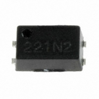
AQY221R2V Panasonic Electric Works, AQY221R2V Datasheet - Page 2

AQY221R2V
Manufacturer Part Number
AQY221R2V
Description
RELAY OPTO AC/DC 40V 250MA 4SSOP
Manufacturer
Panasonic Electric Works
Series
PhotoMOS™ AQYr
Datasheets
1.OAC415-L.pdf
(3 pages)
2.OAC415-L.pdf
(6 pages)
3.AQY221R2VY.pdf
(4 pages)
4.AQY221R2V.pdf
(2 pages)
Specifications of AQY221R2V
Circuit
SPST-NO (1 Form A)
Output Type
AC, DC (RF)
On-state Resistance
1.25 Ohm
Load Current
250mA
Voltage - Input
1.14VDC
Voltage - Load
0 ~ 40 V
Mounting Type
Surface Mount
Termination Style
Gull Wing
Package / Case
4-SSOP
Application
Board tester, medical equipment, multi-point recorder, testing equipment for semiconductor performance
Capacitance, Output
0.8 pF (Typ.)
Contact Form
SPST-NO
Current, Rating
250 mA
Function
Frequency (RF)
Number Of Pins
4
Package Type
SOP
Relay Type
Solid State
Resistance, On-state
0.75 Ohms (Typ.), Output
Temperature, Operating, Minimum
-40 °C
Termination
Surface Mount
Voltage, Rating
40 VAC/VDC
Lead Free Status / RoHS Status
Lead free / RoHS Compliant
Other names
255-2884-3
AQY221R2V
AQY221R2V
Available stocks
Company
Part Number
Manufacturer
Quantity
Price
Part Number:
AQY221R2V
Manufacturer:
NAIS
Quantity:
20 000
Company:
Part Number:
AQY221R2VW
Manufacturer:
PANASONIC
Quantity:
12 000
Company:
Part Number:
AQY221R2VY
Manufacturer:
QUINTIC
Quantity:
24 000
Company:
Part Number:
AQY221R2VY
Manufacturer:
PANASONIC
Quantity:
1 000
2. Electrical characteristics (Ambient temperature: 25°C 77°F)
Notes: 1. Variation possible through combinations of output capacitance and ON resistance.
*1 Turn on/Turn off time
*2 Low on resistance (R type)
REFERENCE DATA
1. Load current vs. ambient temperature
characteristics
Allowable ambient temperature: –40°C to +85°C
Input
Output
Transfer
characteristics
Input
Output
Low capacitance (C type)
400
300
200
120
100
2. Recommendable LED forward current I
0
-10
-20
AQY221R2V
AQY221N2V
Ton
LED operate
current
LED turn off
current
LED dropout
voltage
On resistance
Output
capacitance
Off state leakage
current
Switching
speed
I/O capacitance
Initial I/O isolation
resistance
0
Ambient temperature, °C
Item
20
40
–40°F to +185°F
Turn
on
time*
Turn
off
time*
60
1
1
8085 100
Typical
Maximum
Minimum
Typical
Typical
Maximum
Typical
Maximum
Typical
Maximum
Typical
Maximum
Typical
Maximum
Typical
Maximum
Typical
Maximum
Minimum
Toff
F
Symbol
= 5 mA.
90%
10%
2. Load current vs. Load voltage characteristics
Ambient temperature: 25°C
C
I
R
C
R
I
I
T
T
V
Leak
Fon
Foff
out
on
off
on
iso
iso
F
■ For Dimensions.
■ For Schematic and Wiring Diagrams.
■ For Cautions for Use.
280
240
200
160
120
80
40
0
0
10
AQY221R2V
AQY221R2V
AQY221N2V
0.10 ms
0.08 ms
12.5 pF
0.02 nA
0.9 mA
0.1 mA
0.8 mA
0.75Ω
1.25Ω
18 pF
20
1.35 V (1.14 V at I
Load voltage, V
77°F
30
1,000MΩ
3.0 mA
0.2 ms
0.8 pF
1.5 pF
10 nA
0.5ms
1.5 V
40
RF PhotoMOS (AQY221❍2V)
F
50
= 5 mA)
AQY221N2V
0.01 nA
0.02 ms
0.02 ms
1.0 mA
0.2 mA
0.9 mA
1.0 pF
1.5 pF
12.5Ω
9.5Ω
3. On resistance vs. ambient temperature
characteristics
Measured portion: between terminals 3 and 4
LED current: 5 mA; Load voltage: Max. (DC);
Load current: 250mA (DC) R type, 80mA (DC) C type
25
20
15
10
5
0
For type of connection.
-40
C type (I
R type (I
C type (I
R type (I
C type (I
R type (I
C type (I
Within 1 s on time)
R type (I
Within 1 s on time)
I
V
f = 1 MHz
C type (I
R type (I
C type (I
R
R type (I
R
C type (I
R
R type (I
R
C type (f = 1 MHz, V
R type (f = 1 MHz, V
500V DC
F
-20
B
L
L
L
L
= 0 mA
= 125Ω)
= 40Ω)
= 125Ω)
= 40Ω)
= 0 V
Ambient temperature, °C
0
L
L
L
L
F
F
F
F
F
F
F
F
F
F
Condition*
= 80 mA)
= 250 mA)
= 80 mA)
= 250 mA)
= 50 mA)
= 50 mA)
= 5 mA, I
= 5 mA, I
= 0 mA, V
= 0 mA, V
= 5 mA, V
= 5 mA, V
= 5 mA, V
= 5 mA, V
20
40
AQY221N2V
AQY221R2V
L
L
60
L
L
L
L
L
L
B
B
2
= 80 mA
= 250 mA
= Max.)
= Max.)
= 10 V
= 10 V
= 10 V
= 10 V
= 0 V)
= 0 V)
8085


