2SMES-01 Omron, 2SMES-01 Datasheet
2SMES-01
Specifications of 2SMES-01


Related parts for 2SMES-01

2SMES-01 Summary of contents
Page 1
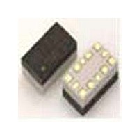
... Packaging Package quantity JEDEC Tray 200 IC Pack 50 ■ Terminal Arrangement +V2 GND +V1 Must operate Must release voltage (V) voltage (V) 90% max. of rated 10% min. of rated voltage voltage RF MEMS Switch Model 2SMES-01 2SMES-01CT RF_1 RF_Com RF_2 Absolute maximum Rated power voltage (V) consumption (μ 2SMES-01 313 ...
Page 2
... Operating: −20°C to 85°C (with no icing or condensation) Ambient temperature Ambient humidity Operating 85% Weight Approx. 0.1 g Note: 1. The above values are initial values. 2. The contact resistance was measured with VDC with a voltage drop method. 2SMES-01 314 RF MEMS Switch 2 GHz 8 GHz --- 30 dB --- ...
Page 3
... These high-frequency characteristics are measured with RF probe (without a mounting board). 3. The high-frequency characteristics depend on the mounting board. Be sure to check operation including durability in actual equipment before use. Isolation 0 −10 −20 −30 −40 (dB) −50 −60 −70 − MEMS Switch Average value (initial Frequency (GHz) 2SMES-01 315 ...
Page 4
... Release Voltage (Ave): 5 Must Release Voltage (3 10 Operating cycles (Million operations) Ambient Temperature vs. Pickup voltage/Release Voltage −30 −20 − Ambient Temperature (°C) 2SMES-01 316 RF MEMS Switch N = 125 Samples (250 contacts operations 125 Samples (250 contacts 100 Pickup Voltage Release Voltage Samples 100 ...
Page 5
... Do not put the RF MEMS Switch in a cold cleaning bath immedi- ately after soldering. Time (s) ) Soldering (T3 230°C min max. --- Vcont_1 RF_1 R RF_com R RF_2 Vcont_2 2SMES-01 2SMES-01 RF MEMS Switch ) Peak value (T4) 2 250°C max. 255°C max. 2SMES-01 317 ...
Page 6
... No.11 No.7 2.55 3.7 4.9 Terminal Arrangement +V2 RF_1 RF_Com GND +V1 RF_2 Evaluation Board Model: 2SMES-01-EVBA 48 3.5 3.5 12.5 25 12.5 3.5 20 11.5 Pattern for RF correction (open) Device mounting area 2SMES-01 318 RF MEMS Switch Mounting PAD Dimensions 12-Terminal Land Grid Array (LGA) (Top View) 0 ...
Page 7
... Claw Securing Force During Automatic Mounting • During automatic insertion of RF MEMS Switches, be sure to set the securing force of each claw to the following so that the RF MEMS Switch's characteristics will be maintained. RF MEMS Switch Via to internal RF ground plane #7 # Direction C: 2.0 N max. 2SMES-01 319 ...
Page 8
... To convert millimeters into inches, multiply by 0.03937. To convert grams into ounces, multiply by 0.03527. OMRON ELECTRONIC COMPONENTS LLC 55 E. Commerce Drive, Suite B Schaumburg, IL 60173 847-882-2288 12/10 Cat. No. X302-E-1 2SMES-01 RF MEMS Switch OMRON ON-LINE Global - http://www.omron.com USA - http://www.components.omron.com Specifications subject to change without notice Printed in USA ...