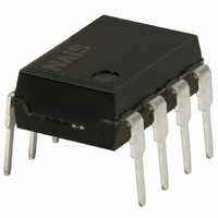
AQH1213 Panasonic Electric Works, AQH1213 Datasheet - Page 4

AQH1213
Manufacturer Part Number
AQH1213
Description
RELAY SSR ZC 0.6A 600V 8 DIP
Manufacturer
Panasonic Electric Works
Series
AQ-Hr
Datasheets
1.OAC415-L.pdf
(3 pages)
2.OAC415-L.pdf
(6 pages)
3.AQH2213.pdf
(3 pages)
4.AQH3213.pdf
(3 pages)
Specifications of AQH1213
Circuit
SPST-NO (1 Form A)
Output Type
AC, Zero Cross
Load Current
600mA
Voltage - Input
1.18VDC
Voltage - Load
0 ~ 600 V
Mounting Type
Through Hole
Termination Style
PC Pin
Package / Case
8-DIP (0.300", 7.62mm), 7 Leads
Brand/series
AQ-H Series
Dielectric Strength
5000 VAC (Between Input & Output)
Function
General Purpose
Number Of Pins
8
Relay Type
Solid State
Standards
cULus, VDE
Temperature, Ambient, Minimum
-30 °C
Temperature, Junction, Maximum
+85 °C
Termination
Through Hole
Lead Free Status / RoHS Status
Lead free / RoHS Compliant
On-state Resistance
-
Lead Free Status / Rohs Status
RoHS Compliant part
Electrostatic Device
Other names
255-1526
255-1526-5
255-1526
255-1526-5
255-1526
Available stocks
Company
Part Number
Manufacturer
Quantity
Price
Company:
Part Number:
AQH1213
Manufacturer:
PANASONIC
Quantity:
12 000
Company:
Part Number:
AQH1213A
Manufacturer:
PANASONIC
Quantity:
12 000
Part Number:
AQH1213A
Manufacturer:
PANASONIC/松下
Quantity:
20 000
Notes: 1. E
AQW61(SOP)
AQW61
AQW65
AQW41
AQW45
AQS22
Series
Series
Series
Type
2. Method of connecting the load at the output is divided into 3 types.
1
: Power source at input side; V
2
3
4
5
6
7
8
1
1
2
3
4
1
2
3
4
Schematic
N.C.
N.O.
16
15
14
13
12
11
10
8
7
6
5
8
7
6
5
9
IN
: Input voltage; I
configu-
Output
ration
1a1b
2b
4a
All Rights Reserved © COPYRIGHT Matsushita Electric Works, Ltd.
AC/DC
AC/DC
AC/DC
Load
F
: LED forward current; I
nection
Con-
—
—
—
(1) Two independent 1 Form A & 1 Form B use
(2) 1 Form A 1 Form B use
(1) Two independent 1 Form B use
(2) 2 Form B use
E
E
E
E
E
E
1
1
1
1
1
1
E
E
E
E
1
2
3
4
IN
: Input current; V
I
I
F
F
I
I
I
I
F1
F2
F1
F2
I
I
I
I
F1
F2
F3
F4
1
2
3
4
1
2
3
4
1
2
3
4
1
2
3
4
1
2
3
4
5
6
7
8
L
: Load voltage; I
16
15
14
13
12
11
10
9
8
7
6
5
8
7
6
5
8
7
6
5
8
7
6
5
I
I
I
I
I
I
I
I
L1
L2
L1
L2
L1
L2
L1
L2
Load
Load
Load
Load
Load
Load
Load
Load
Load
Load
Load
Load
Wiring diagram
I
I
I
I
L
L1
L2
L3
L4
: Load current; R: Current limit resistor.
V
V
V
V
L1
L2
L3
L4
V
V
V
V
V
V
V
V
(AC,DC)
(AC,DC)
(AC,DC)
(AC,DC)
L1
L2
L1
L2
L1
L2
L1
L2
(AC,DC)
(AC,DC)
(AC,DC)
(AC,DC)
(AC,DC)
(AC,DC)
(AC,DC)
(AC,DC)
16
15
14
13
12
11
10
9
8
7
6
5
8
7
6
5
8
7
6
5
8
7
6
5
I
I
I
I
I
I
I
I
I
Load
Load
Load
Load
L1
L2
L1
L2
L1
L1
L2
L1
L2
Load
Load
Load
Load
Load
Load
Load
Load
I
I
I
I
L1
L2
L3
L4
V
V
V
V
L1
L2
L3
L4
(AC,DC)
(AC,DC)
(AC,DC)
(AC,DC)
V
V
V
V
V
V
V
V
L1
L2
L1
L2
L1
L2
L1
L2
(AC,DC)
(AC,DC)
(AC,DC)
(AC,DC)
(AC,DC)
(AC,DC)
(AC,DC)
(AC,DC)


