H5CX-A-N AC100-240 Omron, H5CX-A-N AC100-240 Datasheet - Page 20
H5CX-A-N AC100-240
Manufacturer Part Number
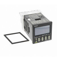
H5CX-A-N AC100-240
Description
RELAY TIMER DGTL SPDT 100/240VAC
Manufacturer
Omron
Series
H5CXr
Specifications of H5CX-A-N AC100-240
Mounting Type
Panel Mount
Relay Type
Integrated
Function
Programmable (Multi-Function)
Circuit
SPDT (1 Form C)
Delay Time
0.001 Sec ~ 9999 Hrs
Output Type
Mechanical Relay
Contact Rating @ Voltage
5A @ 250VAC
Voltage - Supply
100 ~ 240VAC
Termination Style
Screw Terminal
Timing Adjustment Method
DIP Switches
Timing Initiate Method
Input Voltage, Trigger Signal
Timing Range
0.001 s to 9999 Hrs
Supply Voltage
100 V to 240 V
Current Rating (max)
100 mA
Display Type
6 Digit LCD
Product
Digital Timer
Time Range
0.001s-9999hrs
Power Consumption
6.2VA
Reset Time
20ms
Character Size
11.5mm
Time Range Min
0.001s
Supply Voltage Min
100VAC
Connector Type
Screw Terminal
No. Of Digits / Alpha
4
Rohs Compliant
Yes
Lead Free Status / RoHS Status
Lead free / RoHS Compliant
For Use With
PNP/NPN
Lead Free Status / RoHS Status
Lead free / RoHS Compliant, Lead free / RoHS Compliant
Other names
H5CXANAC100240
Z2997
Z2997


Explanation of Functions
Time Range (timr) (Setting possible using DIP switch.)
Set the range to be timed in the range 0.000 s to 9,999 h. Settings of
type ---- h (9,999 h) and ---- min (9,999 min) cannot, however, be
made with the DIP switch. Use the operation keys if these settings
are required.
Timer Mode (timm) (Setting possible using DIP switch.)
Set either the elapsed time (UP) or remaining time (DOWN) mode.
Output Mode (outm) (Setting possible using DIP switch.)
Set the output mode. The possible settings are A, A-1, A-2, A-3, b, b-
1, d, E, F, and Z. Only output modes A, A-2, E, and F can be set
using the DIP switch. Use the operation keys if a different setting is
required. (For details on output mode operation, refer to Timing
Charts on page 22.)
Output Time (otim)
When using one-shot output, set the output time for one-shot output
(0.01 to 99.99 s). One-shot output can be used only if the selected
output mode is A, A-1, A-2, b, or b-1. If the output time is set to 0.00,
hold is displayed, and the output is held.
Key Protect Level (kypt)
Set the key protect level.
When the key-protect switch is set to ON, it is possible to prevent setting errors by prohibiting the use of certain operation keys by specifying the
key protect level (KP-1 to KP-5). The key protect indicator is lit while the key-protect switch is set to ON.
Note: Changing mode to timer/twin timer selection mode (
KP-1
(default setting)
KP-2
KP-3
KP-4
KP-5
Note: Factory-set to OFF
(See note)
Level
OFF
ON
Key protect indicator
Meaning
No
No
No
No
No
Changing mode
(See note.)
MODE
+
1
Yes
Yes
Yes
Yes
No
1 s min.) or function setting mode (
Switching display
during operation
Input Signal Width (iflt) (Setting possible using DIP
switch.)
Set the minimum signal input width (20 ms or 1 ms) for signal, reset,
and gate inputs. The same setting is used for all external inputs (sig-
nal, reset, and gate inputs). If contacts are used for the input signal,
set the input signal width to 20 ms. Processing to eliminate chatter-
ing is performed for this setting.
NPN/PNP Input Mode (imod)
Select either NPN input (no-voltage input) or PNP input (voltage
input) as the input format. The same setting is used for all external
inputs. For details on input connections, refer to Input Connections
on page 9.
Display Color (colr)
Set the color used for the present value.
red
grn
r-g
g-r
Red (fixed)
Green (fixed)
Red
Green
Details
Output OFF
Yes
No
Yes
No
No
Reset key
MODE
3 s min.).
Green
Red
Yes
Yes
No
No
No
H5CX-A/-L
Output ON
Up/down key
20
Related parts for H5CX-A-N AC100-240
Image
Part Number
Description
Manufacturer
Datasheet
Request
R

Part Number:
Description:
Digital Timer
Manufacturer:
Omron Corporation
Datasheet:
Part Number:
Description:
Relay; E-Mech; Timing; Multi-Function; Cur-Rtg 5A; Ctrl-V 100-240AC; Socket Mnt; 8 Pin
Manufacturer:
Omron Automation
Datasheet:
Part Number:
Description:
Relay; E-Mech; Timing; Multi-Function; Cur-Rtg 5A; Ctrl-V 100-240AC; Socket Mnt; 11 Pin
Manufacturer:
Omron Automation
Datasheet:
Part Number:
Description:
Relay; E-Mech; Timing; Multi-Function; Cur-Rtg 5A; Ctrl-V 24/12-24AC/DC; Screw; 11 Pin
Manufacturer:
Omron Automation
Datasheet:
Part Number:
Description:
Relay; E-Mech; Timing; Multi-Function; Cur-Rtg 5A; Ctrl-V 24/12-24AC/DC; Socket Mnt
Manufacturer:
Omron Automation
Datasheet:
Part Number:
Description:
G6S-2GLow Signal Relay
Manufacturer:
Omron Corporation
Datasheet:
Part Number:
Description:
Compact, Low-cost, SSR Switching 5 to 20 A
Manufacturer:
Omron Corporation
Datasheet:
Part Number:
Description:
Manufacturer:
Omron Corporation
Datasheet:
Part Number:
Description:
Manufacturer:
Omron Corporation
Datasheet:
Part Number:
Description:
Manufacturer:
Omron Corporation
Datasheet:
Part Number:
Description:
Manufacturer:
Omron Corporation
Datasheet: