LT4H-DC24VS Panasonic Electric Works, LT4H-DC24VS Datasheet - Page 16
LT4H-DC24VS
Manufacturer Part Number
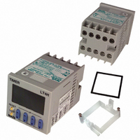
LT4H-DC24VS
Description
TIMER RELAY DIG 24VDC SCREW TERM
Manufacturer
Panasonic Electric Works
Series
LT4Hr
Datasheet
1.LT4H-DC24VS.pdf
(39 pages)
Specifications of LT4H-DC24VS
Lead Free Status / RoHS Status
Lead free / RoHS Compliant
Other names
255-1217


PRECAUTIONS IN USING THE LT4H SERIES
Once the wiring to be used is completely
installed and prior to installing this timer,
confirm that there is complete insulation
between the wires connected to the
power terminals (2 each) and the wires
connected to each input terminal. If the
power and input lines are not insulated, a
short-circuit may occur inside the timer
and result in internal damage.
In addition, when moving your equipment
to a new installation location, confirm
that there is no difference in environmen-
tal conditions as compared to the previ-
ous location.
shorting of each input terminal with the
common terminal (terminal Q for 8-pin
types, terminal E for 11-pin types and
terminal
Never connect other terminals or volt-
ages higher than 40V DC, because it
may destroy the internal circuitry.
5) Transistor output
(1) Since the transistor output is insulat-
Note: With the 8-pin type, there is no diode
48
4) The input signal is applied by the
As NPN output
As PNP output
ed from the internal circuitry by a pho-
tocoupler, it can be used as an NPN
output or PNP (equal value) output.
(The above example is 11-pin type)
between points I and O.
6
( Fig. A ) Good example
( Fig. B ) Bad example
for screw terminal types).
AC power supply
AC power supply
AC power supply
Load’s power supply
Load’s power supply
{
{
LT4H timer
Load
LT4H timer
Insulation transformer
Insulation transformer
Single coil transformer
Timer
Timer
Timer
O
O
Load
(+)
(–)
(+)
(–)
(+)
(–)
(–)
(–)
(–)
Alternative
current flow
( e.g. , sensor )
( e.g. , sensor )
( e.g. , sensor )
Input device
Input device
Input device
I
I
(2) Use the diode connected to the out-
put transistor’s collector for absorbing
the reverse voltage from induced loads.
6) When wiring, use shielded wires or
metallic wire tubes, and keep the wire
lengths as short as possible.
7) For the load of the controlled output,
make sure that it is lower than the rated
control capacity.
4. Operation of LT4H digital timer
1) Turning on and off the power supply
while operating in A2* (Power on delay
2) or G (Totalizing On delay) will result in
a timer error to be generated due to the
characteristics of the internal circuitry.
Therefore, use the start input or stop
input.
* Not related to the start input.
2) When controlling the timer by turning
on the power supply, use only A (Power
on delay 1) or A2 (Power on delay 2).
Use of other modes in this situation will
result in timer errors. When using the
other modes, control the timer with the
start input or stop input.
5. Operation mode and time range set-
ting
The operation mode and time range can
be set with the DIP switches on the side
of the timer. Make the DIP switch set-
tings before installing the timer on the
panel.
The operation mode of LT4H-W series
can be set with the keys and switches on
the front of the timer.
6. Conditions of usage
1) Avoid locations subject to flammable
or corrosive gases, excessive dust, oil,
vibrations, or excessive shocks.
2) Since the cover of the timer is made of
polycarbonate resin, avoid contact with
or use in environments containing methyl
alcohol, benzene, thinners, and other
organic solvents; and ammonia, caustic
sodas, and other alkaline substances.
3) If power supply surges exceed the val-
ues given below, the internal circuits may
become damaged. Be sure to use surge
absorbing element to prevent this from
happening.
Operating voltage Surge voltage (peak value)
Diode rating:
I
V
F
R
(forward current): 1 A
24V AC type
(reverse voltage): 600 V
AC type
DC type
LT4H timer
power supply
Load’s
6,000V
1,000V
Inductive load
• Surge wave form
[± (1.2 × 50) µs uni-polar full wave voltage]
4) Regarding external noise, the values
below are considered the noise-resistant
voltages. If voltages rise above these
values, malfunctions or damage to the
internal circuitry may result, so take the
necessary precautions.
Noise wave form (noise simulator)
Rise time: 1 ns
Pulse width: 1 µs, 50 ns
Polarity: ±
Cycle: 100 cycles/second
5) When connecting the operating power
supply, make sure that no leakage cur-
rent enters the timer. For example, when
performing contact protection, if set up
like that of fig. A, leaking current will
pass through C and R, enter the unit,
and cause incorrect operation. The fig. B
shows the correct setup.
Operating power supply
Operating power supply
voltage
Noise
100
90
50
30
0
0
Power supply terminals
AC type
1,500V
1.2
Leakage current
Time (µs)
R
Peak
24V AC type
(Fig. A)
(Fig. B)
DC type
1,000V
C
R
C
50
terminals
600V
Input
T
T
Related parts for LT4H-DC24VS
Image
Part Number
Description
Manufacturer
Datasheet
Request
R

Part Number:
Description:
TIMER RELAY DIGITAL 240VAC SCREW
Manufacturer:
Panasonic Electric Works
Datasheet:

Part Number:
Description:
TIMER RELAY DIGITAL 240VAC 11PIN
Manufacturer:
Panasonic Electric Works
Datasheet:
Part Number:
Description:
TIMER RELAY DIG 24VDC OCT 11PIN
Manufacturer:
Panasonic Electric Works
Datasheet:

Part Number:
Description:
Timer Multifunction
Manufacturer:
NAIS
Datasheet:

Part Number:
Description:
TIMER DIGITAL 24VDC SCREW TERM
Manufacturer:
Panasonic Electric Works
Datasheet:
Part Number:
Description:
Manufacturer:
Panasonic Electric Works
Datasheet:
Part Number:
Description:
Manufacturer:
Panasonic Electric Works
Datasheet:

Part Number:
Description:
CONN SOCKET P4 .4MM 50POS SMD
Manufacturer:
Panasonic Electric Works
Datasheet:
Part Number:
Description:
CONN SOCKET .8MM 16POS SMD
Manufacturer:
Panasonic Electric Works
Datasheet:
Part Number:
Description:
CONN HEADER .8MM 16POS SMD
Manufacturer:
Panasonic Electric Works
Datasheet:
Part Number:
Description:
CONN SOCKET .8MM 20POS SMD
Manufacturer:
Panasonic Electric Works
Datasheet:
Part Number:
Description:
CONN SOCKET .8MM 20POS SMD
Manufacturer:
Panasonic Electric Works
Datasheet:
Part Number:
Description:
CONN HEADER .8MM 20POS SMD
Manufacturer:
Panasonic Electric Works
Datasheet:
Part Number:
Description:
CONN SOCKET .8MM 22POS SMD
Manufacturer:
Panasonic Electric Works
Datasheet:
Part Number:
Description:
CONN SOCKET .8MM 30POS SMD
Manufacturer:
Panasonic Electric Works
Datasheet: