H5CX-ASD-N-DC12-24/AC24 Omron, H5CX-ASD-N-DC12-24/AC24 Datasheet - Page 48
H5CX-ASD-N-DC12-24/AC24
Manufacturer Part Number
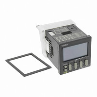
H5CX-ASD-N-DC12-24/AC24
Description
RELAY TIMER DGTL TRANS 12-24VDC
Manufacturer
Omron
Series
H5CXr
Specifications of H5CX-ASD-N-DC12-24/AC24
Relay Type
Integrated
Function
Programmable (Multi-Function)
Delay Time
0.001 Sec ~ 9999 Hrs
Output Type
Transistor
Voltage - Supply
12 ~ 24VDC, 24VAC
Mounting Type
Panel Mount
Termination Style
Screw Terminal
Timing Adjustment Method
DIP Switches
Timing Initiate Method
Input Voltage, Trigger Signal
Timing Range
0.001 s to 9999 Hrs
Supply Voltage
12 V to 24 V
Current Rating (max)
100 mA
Display Type
4 Digit LCD Backlight
Product
Digital Timer
Lead Free Status / RoHS Status
Lead free / RoHS Compliant
Circuit
-
Contact Rating @ Voltage
-
Lead Free Status / Rohs Status
Lead free / RoHS Compliant
Other names
H5CXASDNDC1224AC24
Z3001
Z3001


■ Precautions for Correct Use
Power Supplies
Turn the power ON and OFF using a relay with a rated capacity of 10
A minimum to prevent contact deterioration due to inrush current
caused by turning the power ON and OFF.
Be sure that the capacity of the power supply is large enough,
otherwise the Timer may not start due to inrush current that may flow
for an instant when the Timer is turned on.
When turning the power ON and OFF, input signal reception is
possible, unstable, or impossible as shown in the diagram below.
Timer Control with Power Start
To allow for the startup time of peripheral devices (sensors, etc.), the
H5CX starts timing operation between 200 ms to 250 ms after power
is turned ON. For this reason, in operations where timing starts from
power ON, the time display will actually start from 250 ms. If the set
value is 249 ms or less, the time until output turns ON will be a fixed
value between 200 and 250. (Normal operation is possible for set
value of 250 ms or more.) In applications where a set value of
249 ms or less is required, use start timing with signal input.
When the H5CX is used with power start in F mode or F-1 mode (i.e.,
accumulative operation with output on hold), there will be a timer
error (approximately 100 ms each time the H5CX is turned ON) due
to the characteristics of the internal circuitry. Use the H5CX with
signal start if timer accuracy is required.
Transistor Output
The transistor output of the H5CX is insulated from the internal
circuitry by a photocoupler, so the transistor output can be used as
both NPN and PNP output.
The diode connected to the collector of the output transistor is used
to absorb inverted voltage that is generated when an inductive load
is connected to the H5CX.
Power
supply
NPN Output
Timer
Power for load
Power for load
ON
OFF
Input
+
+
Impossible
Load
200 ms
Inductive load
Unstable
0 to 50 ms
PNP Output
Load
Power for load
Possible
+
5 ms
Unstable
0 to 500 ms
Impossible
Response Delay Time When Resetting
(Transistor Output)
The following table shows the delay from when the reset signal is
input until the output is turned OFF.
Power Failure Backup
All data is stored in the EEPROM when there is a power failure. The
EEPROM can be overwritten more than 100,000 times.
■ Conformance to EN/IEC
There is no insulation between power supply and input terminals
(except for H5CX-A11/-A11S).
Basic insulation between power supply and output terminals, and
between input terminals and output terminals.
When double insulation or reinforced insulation is required, apply
double insulation or reinforced insulation defined in IEC 60664 that is
suitable for the maximum operating voltage with clearances or solid
insulation.
1 ms
20 ms
A-3, b-1, F, F-1 mode When power is turned OFF.
Other mode
Minimum reset signal width
Operating mode
Standards
When settings are changed.
0.8 to 1.2 ms
15 to 25 ms
Overwriting timing
Output delay time
(Reference value)
H5CX-B
48
Related parts for H5CX-ASD-N-DC12-24/AC24
Image
Part Number
Description
Manufacturer
Datasheet
Request
R

Part Number:
Description:
Scrw Term,Trans OUT, Multi-Fnc
Manufacturer:
Omron

Part Number:
Description:
G6S-2GLow Signal Relay
Manufacturer:
Omron Corporation
Datasheet:
Part Number:
Description:
Compact, Low-cost, SSR Switching 5 to 20 A
Manufacturer:
Omron Corporation
Datasheet:
Part Number:
Description:
Manufacturer:
Omron Corporation
Datasheet:
Part Number:
Description:
Manufacturer:
Omron Corporation
Datasheet:
Part Number:
Description:
Manufacturer:
Omron Corporation
Datasheet:
Part Number:
Description:
Manufacturer:
Omron Corporation
Datasheet:
Part Number:
Description:
Manufacturer:
Omron Corporation
Datasheet:
Part Number:
Description:
Manufacturer:
Omron Corporation
Datasheet: