H3CR-A8E AC100-240/DC100-125 Omron, H3CR-A8E AC100-240/DC100-125 Datasheet - Page 21
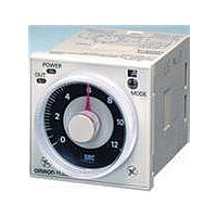
H3CR-A8E AC100-240/DC100-125
Manufacturer Part Number
H3CR-A8E AC100-240/DC100-125
Description
RELAY ANALOG SET DPDT 8PIN
Manufacturer
Omron
Series
H3CR-Ar
Datasheets
1.H3CR-A8_AC24-48DC12-48.pdf
(21 pages)
2.H3CR-A-AC100-240DC100-125.pdf
(29 pages)
3.H3CR-A_AC100-240DC100-125.pdf
(22 pages)
Specifications of H3CR-A8E AC100-240/DC100-125
Mounting Type
Socket
Relay Type
Integrated
Function
Programmable (Multi-Function)
Circuit
DPDT (2 Form C)
Delay Time
0.05 Sec ~ 300 Hrs
Output Type
Mechanical Relay
Contact Rating @ Voltage
5A @ 250VAC
Voltage - Supply
100 ~ 240VAC, 100 ~ 125VDC
Termination Style
8 Pin Socketable
Timing Adjustment Method
Hand Dial
Timing Initiate Method
Input Voltage
Timing Range
0.05 s to 300 Hrs
Supply Voltage
100 VAC to 240 VAC, 100 VDC to 125 VDC
Accuracy
+/- 0.2 %
Current Rating (max)
5 A
Display Type
Hand Dial
Operating Temperature Range
- 10 C to + 55 C
Time Range
0.05 Sec. To 300 Hr.
Supply Voltage Ac, Min
100VAC
No. Of Timing Functions
4
Body Material
94B3297
No. Of Pins
8
Supply Voltage Ac, Max
240VAC
Load Current Rms Max
5A
Rohs Compliant
Yes
Lead Free Status / RoHS Status
Lead free / RoHS Compliant
Lead Free Status / RoHS Status
Lead free / RoHS Compliant, Lead free / RoHS Compliant
Other names
H3CR-A8EAC100-240/DC100-125
H3CRA8EAC100240DC100125
H3CRA8EAC100240DC100125
Q3619148
H3CRA8EAC100240DC100125
H3CRA8EAC100240DC100125
Q3619148


Relationship between Input and Power
Supply Circuits (H3CR-A@/-A@S)
An appropriate input is applied to the input signal terminals of the
H3CR-A@/-A@S when one of the input terminals is short-circuited
with the common terminal (terminal 2) for the input signals. Never
use terminal 10 as the common terminal for this purpose, otherwise
the internal circuit of the Timer will be damaged.
Do not connect a relay or any other load between input terminals,
otherwise the internal circuit of the Timer will be damaged due to the
high-tension voltage applied to the input terminals.
Relationship between Input and Power
Supply Circuits (H3CR-AP)
Since the input circuit and the power supply circuit are configured
independently, the input circuit can be turned ON or OFF irrespective
of the ON/OFF state of the power supply.
It must be noted that a voltage equivalent to the power supply voltage
is applied to the input circuit.
Incorrect
Correct
AC or DC
power supply
AC or DC
power supply
AC or DC
power supply
AC/DC
power
supply
Input
contact
ALL DIMENSIONS SHOWN ARE IN MILLIMETERS.
To convert millimeters into inches, multiply by 0.03937. To convert grams into ounces, multiply by 0.03527.
H3CR-AP
Ry
Input circuit
Input terminal
Input terminal
Input terminal
In the interest of product improvement, specifications are subject to change without notice.
5, 6, 7
G, S, R
5, 6, 7
G, S, R
5, 6, 7
G, S, R
Power supply
circuit
H3CR-A
H3CR-A
H3CR-A
2
10
10
2
2
10
If a relay or transistor is connected to two or more Timers, the input
terminals of those Timers must be wired properly so that they will not
be different in phase or the terminals will be short-circuited to one
another (refer to the figures below).
Common to All H3CR-A Models
With the H3CR-AP, input wires must be as short as possible. If the
floating capacity of wires exceeds 1,200 pF (approx. 10 m for cables
with 120 pF/m), the operation will be affected. Pay particular
attention when using shielded cables.
The H3CR-A@S transistor output is isolated from the internal
circuitry by a photocoupler. Therefore, either NPN or PNP output is
possible.
Incorrect
Correct
Contact or transistor for
external input signal
Contact or transistor for
external input signal
6
7
6
7
6
7
6
7
H3CR-AP
H3CR-AP
H3CR-AP
H3CR-AP
2
2
10
10
10
2
2
10
Short-circuit current
Short-circuit current
Power supply
H3CR-A
Power supply
21
Related parts for H3CR-A8E AC100-240/DC100-125
Image
Part Number
Description
Manufacturer
Datasheet
Request
R

Part Number:
Description:
G6S-2GLow Signal Relay
Manufacturer:
Omron Corporation
Datasheet:
Part Number:
Description:
Compact, Low-cost, SSR Switching 5 to 20 A
Manufacturer:
Omron Corporation
Datasheet:
Part Number:
Description:
Manufacturer:
Omron Corporation
Datasheet:
Part Number:
Description:
Manufacturer:
Omron Corporation
Datasheet:
Part Number:
Description:
Manufacturer:
Omron Corporation
Datasheet:
Part Number:
Description:
Manufacturer:
Omron Corporation
Datasheet:
Part Number:
Description:
Manufacturer:
Omron Corporation
Datasheet:
Part Number:
Description:
Manufacturer:
Omron Corporation
Datasheet: