LPS0800H4700JB Vishay, LPS0800H4700JB Datasheet - Page 2
LPS0800H4700JB
Manufacturer Part Number
LPS0800H4700JB
Description
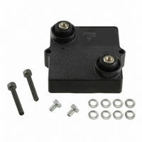
RESISTOR HEAT SINK 470 OHM 800W
Manufacturer
Vishay
Series
LPS 800r
Type
Power Resistor for Mounting onto a Heatsink Thick Filmr
Datasheet
1.LPS0800H4R70JB.pdf
(4 pages)
Specifications of LPS0800H4700JB
Resistance
470 Ohms
Power Rating
800 Watts
Temperature Coefficient
±150ppm/°C
Resistance (ohms)
470
Power (watts)
800W
Composition
Thick Film
Features
Non-Inductive
Tolerance
±5%
Coating, Housing Type
Silicon Coated
Mounting Feature
Flanges
Size / Dimension
2.547" L x 2.362" W (64.70mm x 60.00mm)
Height
0.598" (15.20mm)
Lead Style
M4 Threaded
Package / Case
Box
Operating Temperature Range
- 55 C to + 175 C
Dimensions
57 mm W x 60 mm L x 25.2 mm H
Resistance Tolerance
± 5%
Resistor Element Material
Thick Film
Resistor Case Style
Heat Sinkable Planar
Lead Free Status / RoHS Status
Lead free / RoHS Compliant
Lead Free Status / RoHS Status
Lead free / RoHS Compliant
Other names
LPS 800 H 470U 5% BO15 E
LPS-470C
LPS-470C


www.vishay.com
68
LPS 800
Vishay Sfernice
RECOMMENDATIONS FOR MOUNTING ONTO A HEATSINK
• Surfaces in contact must be carefully cleaned.
• The heatsink must have an acceptable flatness: From 0.05 mm to 0.1 mm/100 mm.
• Roughness of the heatsink must be around 6.3 µm. In order to improve thermal conductivity, surfaces in contact (alumina,
• The fastening of the resistor to the heatsink is under pressure control of two screws tightened at 2 Nm for full power availability.
• The following accessories are supplied with each product: 2 screws CHC M4 * 25 class 8.8 and 2 M4 contact lock washers for
CHOICE OF THE HEATSINK
The user must choose the heatsink according to the working conditions of the component (power, room temperature). Maximum
working temperature must not exceed 175 °C. The dissipated power is simply calculated by the following ratio:
Example:
PERFORMANCE
TESTS
Momentary Overload
Rapid Temperature Change
Load Life
Humidity (Steady State)
Vibration
Climatic Sequence
Tightening Torque on Heatsink
heatsink) should be coated with a silicone grease (type SI 340 from Rhône-Poulenc or Dow 340 from Dow Corning) or a thermal
film (type Q Pad II) easier and faster to install than the grease.
P:
ΔT:
R
R
R
ΔT ≤ 175 °C - 50 °C = 125 °C
R
R
R
TH (j - c)
TH (c - a)
TH (c - a)
TH (j - c)
TH (j - c)
TH (c - a)
:
:
+ R
= 0.112 °C/W
for LPS 800 power dissipation 180 W at + 50 °C room temperature.
= 0.69 °C/W - 0.112 °C/W = 0.578 °C/W
Expressed in W
Difference between maximum working temperature and room temperature
Thermal resistance value measured between resistive layer and outer side of the resistor. It is the thermal
resistance of the component: (see specifications environmental paragraph).
Thermal resistance value measured between outer side of the resistor and room temperature. It is the thermal
resistance of the thermal interface, the heatsink (type, shape) and the quality of the fastening device.
TH (c - a)
=
ΔT
-------
P
=
Power Resistor for Mounting onto a Heatsink
125
--------- -
180
= 0.69 °C/W
For technical questions, contact:
IEC 60115-1/IEC 60068-2-14 Test Na
MIL STD 202 Method 204 Cond. D
Thick Film Technology
1000 h (90/30) P
56 days RH 95 %/40 °C
P
U
- 55 °C to + 175 °C
=
max.
(10 g; 5/500 Hz)
CONDITIONS
--------------------------------------------------------- -
[
IEC 60115-1
1.5 x P
IEC 60115-1
IEC 60115-1
IEC 60115-1
(55/175/56)
R
50 cycles
≤ U
TH (j - c)
L
heatsink mounting,
2 screws TH M4 * 6/6 and 2 M4 contact lock washers for
connections.
r
= 5000 V
/10 s
ΔT
+
r
at 85 °C
R
TH (c - a)
sfer@vishay.com
]
LPS 800
2 Nm
± (0.25 % + 0.05 Ω)
± (0.25 % + 0.05 Ω)
± (0.5 % + 0.05 Ω)
± (0.5 % + 0.05 Ω)
± (0.5 % + 0.05 Ω)
REQUIREMENTS
± (1 % + 0.05 Ω)
Document Number: 50054
Revision: 27-Oct-10
Related parts for LPS0800H4700JB
Image
Part Number
Description
Manufacturer
Datasheet
Request
R

Part Number:
Description:
357-036-542-201 CARDEDGE 36POS DL .156 BLK LOPRO
Manufacturer:
Vishay
Datasheet:
Part Number:
Description:
357-036-542-201 CARDEDGE 36POS DL .156 BLK LOPRO
Manufacturer:
Vishay
Datasheet:
Part Number:
Description:
357-036-542-201 CARDEDGE 36POS DL .156 BLK LOPRO
Manufacturer:
Vishay
Datasheet:
Part Number:
Description:
357-036-542-201 CARDEDGE 36POS DL .156 BLK LOPRO
Manufacturer:
Vishay
Datasheet:
Part Number:
Description:
357-036-542-201 CARDEDGE 36POS DL .156 BLK LOPRO
Manufacturer:
Vishay
Datasheet:
Part Number:
Description:
357-036-542-201 CARDEDGE 36POS DL .156 BLK LOPRO
Manufacturer:
Vishay
Datasheet:
Part Number:
Description:
357-036-542-201 CARDEDGE 36POS DL .156 BLK LOPRO
Manufacturer:
Vishay
Datasheet:
Part Number:
Description:
357-036-542-201 CARDEDGE 36POS DL .156 BLK LOPRO
Manufacturer:
Vishay
Datasheet:
Part Number:
Description:
357-036-542-201 CARDEDGE 36POS DL .156 BLK LOPRO
Manufacturer:
Vishay
Datasheet:
Part Number:
Description:
357-036-542-201 CARDEDGE 36POS DL .156 BLK LOPRO
Manufacturer:
Vishay
Datasheet:
Part Number:
Description:
357-036-542-201 CARDEDGE 36POS DL .156 BLK LOPRO
Manufacturer:
Vishay
Datasheet:
Part Number:
Description:
357-036-542-201 CARDEDGE 36POS DL .156 BLK LOPRO
Manufacturer:
Vishay
Datasheet:
Part Number:
Description:
357-036-542-201 CARDEDGE 36POS DL .156 BLK LOPRO
Manufacturer:
Vishay
Datasheet:
Part Number:
Description:
357-036-542-201 CARDEDGE 36POS DL .156 BLK LOPRO
Manufacturer:
Vishay
Datasheet:
Part Number:
Description:
357-036-542-201 CARDEDGE 36POS DL .156 BLK LOPRO
Manufacturer:
Vishay
Datasheet: