RH0102K500FE02 Vishay, RH0102K500FE02 Datasheet - Page 4
RH0102K500FE02
Manufacturer Part Number
RH0102K500FE02
Description
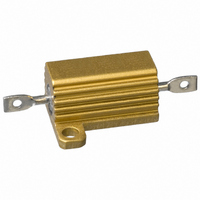
RES 2.5K OHM 10W ALUM HOUSED WW
Manufacturer
Vishay
Series
RHr
Specifications of RH0102K500FE02
Resistance
2.5 KOhms
Power Rating
10 Watts
Temperature Coefficient
±20ppm/°C
Resistance (ohms)
2.5K
Power (watts)
10W
Composition
Wirewound
Tolerance
±1%
Coating, Housing Type
Aluminum Housed
Mounting Feature
Flanges
Size / Dimension
0.750" L x 0.800" W (19.05mm x 20.32mm)
Height
0.390" (9.91mm)
Lead Style
Solder Lugs
Package / Case
Axial, Box
Operating Temperature Range
- 55 C to + 250 C
Dimensions
20.32 mm W x 19.05 mm L x 9.91 mm H
Product
Power Resistors Wire Wound Aluminum Housed
Resistance Tolerance
± 1%
Resistor Element Material
Wirewound
Resistor Case Style
Axial Lugs
Lead Free Status / RoHS Status
Lead free / RoHS Compliant
Lead Free Status / RoHS Status
Lead free / RoHS Compliant, Lead free / RoHS Compliant
Other names
RHRB-2.5K


RH, NH
Vishay Dale
MATERIAL SPECIFICATIONS
Element: Copper-nickel alloy or nickel-chrome alloy,
depending on resistance value
Core: Ceramic, steatite or alumina, depending on physical
size
Encapsulant: Silicone molded construction
Housing: Aluminum with hard anodic coating
End Caps: Stainless steel
Standard Terminals: For RH005 through RH050 size
terminal finish - Tin/lead is 60/40 Sn/Pb w/Nickel underplate
and Lead (Pb)-free is Ni/Pd/Au, finish is on copper clad
steel core terminal. For RH100 and RH250 terminals are
threaded stainless steel.
Part Marking: Dale, model, wattage, value, tolerance, date
code
NH NON-INDUCTIVE
Models of equivalent physical and electrical specifications
are available with non-inductive (Aryton-Perry) winding.
They are identified by substituting the letter N for R in the
model number (NH005, for example).
www.vishay.com
4
PERFORMANCE
TEST
Thermal Shock
Short Time Overload
Dielectric Withstanding
Voltage
Temperature
Moisture Resistance
Shock, Specified Pulse
Vibration, High Frequency
Load Life
Terminal Strength
Rated power applied until thermally stable, then a minimum of 15 min at - 55 °C
5 x rated power for 5 s
1000 V
4500 V
250 °C for 2 h
MIL-STD-202 Method 106, 7b not applicable
MIL-STD-202 Method 213, 100 g’s for 6 ms, 10 shocks
Frequency varied 10 Hz to 2000 Hz, 20 g peak, 2 directions 6 h each
1000 h at rated power, + 25 °C, 1.5 h “ON”, 0.5 h “OFF”
30 s, 5 pound pull test for RH005 and RH010, 10 pound pull test for other sizes;
torque test - 24 pound inch for RH100 and 32 pound inch for RH250
rms
rms
For technical questions, contact:
Wirewound Resistors, Industrial Power,
for RH005, RH010 and RH025; 2000 Vrms for RH050;
for RH100 and RH250; duration 1 min
Aluminum Housed, Chassis Mount
CONDITIONS OF TEST
ww2bresistors@vishay.com
SPECIAL MODIFICATIONS
A number of special modifications to the aluminum housed
resistor
modifications include:
• Terminal configurations and materials
• Resistance values and tolerances
• Low resistance temperature coefficient (RTC)
• Housing configuration
• Threaded mounting holes
• Preconditioning and other additional testing
APPLICABLE MIL SPECIFICATIONS
Vishay RH and NH resistors are listed as qualified on the
MIL-PRF-18546 QPL. MIL-PRF-18546 qualified, type RE
resistors can be found at:
style
are
available
www.vishay.com/doc?30282
upon
Document Number: 30201
± (0.5 % + 0.05 ) R
± (0.5 % + 0.05 ) R
± (0.2 % + 0.05 ) R
± (0.5 % + 0.05 ) R
± (1.0 % + 0.05 ) R
± (0.2 % + 0.05 ) R
± (0.2 % + 0.05 ) R
± (1.0 % + 0.05 ) R
± (0.2 % + 0.05 ) R
TEST LIMITS
Revision: 02-Mar-11
request.
Special
Related parts for RH0102K500FE02
Image
Part Number
Description
Manufacturer
Datasheet
Request
R

Part Number:
Description:
357-036-542-201 CARDEDGE 36POS DL .156 BLK LOPRO
Manufacturer:
Vishay
Datasheet:
Part Number:
Description:
357-036-542-201 CARDEDGE 36POS DL .156 BLK LOPRO
Manufacturer:
Vishay
Datasheet:
Part Number:
Description:
357-036-542-201 CARDEDGE 36POS DL .156 BLK LOPRO
Manufacturer:
Vishay
Datasheet:
Part Number:
Description:
357-036-542-201 CARDEDGE 36POS DL .156 BLK LOPRO
Manufacturer:
Vishay
Datasheet:
Part Number:
Description:
357-036-542-201 CARDEDGE 36POS DL .156 BLK LOPRO
Manufacturer:
Vishay
Datasheet:
Part Number:
Description:
357-036-542-201 CARDEDGE 36POS DL .156 BLK LOPRO
Manufacturer:
Vishay
Datasheet:
Part Number:
Description:
357-036-542-201 CARDEDGE 36POS DL .156 BLK LOPRO
Manufacturer:
Vishay
Datasheet:
Part Number:
Description:
357-036-542-201 CARDEDGE 36POS DL .156 BLK LOPRO
Manufacturer:
Vishay
Datasheet:
Part Number:
Description:
357-036-542-201 CARDEDGE 36POS DL .156 BLK LOPRO
Manufacturer:
Vishay
Datasheet:
Part Number:
Description:
357-036-542-201 CARDEDGE 36POS DL .156 BLK LOPRO
Manufacturer:
Vishay
Datasheet:
Part Number:
Description:
357-036-542-201 CARDEDGE 36POS DL .156 BLK LOPRO
Manufacturer:
Vishay
Datasheet:
Part Number:
Description:
357-036-542-201 CARDEDGE 36POS DL .156 BLK LOPRO
Manufacturer:
Vishay
Datasheet:
Part Number:
Description:
357-036-542-201 CARDEDGE 36POS DL .156 BLK LOPRO
Manufacturer:
Vishay
Datasheet:
Part Number:
Description:
357-036-542-201 CARDEDGE 36POS DL .156 BLK LOPRO
Manufacturer:
Vishay
Datasheet:
Part Number:
Description:
357-036-542-201 CARDEDGE 36POS DL .156 BLK LOPRO
Manufacturer:
Vishay
Datasheet: