TMC50-250 Huntington Electric Inc., TMC50-250 Datasheet
TMC50-250
Manufacturer Part Number
TMC50-250
Description
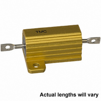
RES ALUM HOUSED 250 OHM 50W 1%
Manufacturer
Huntington Electric Inc.
Series
TMCr
Datasheet
1.TMC10-75.pdf
(1 pages)
Specifications of TMC50-250
Resistance (ohms)
250
Power (watts)
50W
Composition
Wirewound
Temperature Coefficient
±20ppm/°C
Tolerance
±1%
Coating, Housing Type
Aluminum Housed
Mounting Feature
Flanges
Size / Dimension
1.968" L x 1.140" W (49.99mm x 28.96mm)
Height
0.615" (15.62mm)
Lead Style
Solder Lugs
Package / Case
Axial, Box
Lead Free Status / RoHS Status
Lead free / RoHS Compliant
Other names
TMC-50-250-1%
STANDARD
TMC-5
TMC-10
TMC-25
TMC-50
TMC-50L
Huntington Electric’s high power aluminum housed resistors use centerless ground
ceramic cores for uniform heat distribution. Molded in a special high temperature materi-
al and mounted in an extruded aluminum finned housing, these designs provide maxi-
mum power dissipation and reliability. They have tinned copperweld leads for solderabili-
ty, and meet or exceed MIL-R-18546, including “N” characteristic, and MIL-R-39009.
TYPE
TMC-10
TMC-25
TMC-50
TMC -5
Heat Sink Requirements:
Other power ratings are available to 250 Watts. Please consult factory for
HUNTINGTON ELECTRIC, INC. P.O. BOX 366
TYPE
Temperature Coefficient
Operating Temp Range:
TMC
Dielectric Strength:
±.005 (0.1)
(10.8)
(14.3)
(18.3)
(39.7)
1.563
.444
.562
.719
RER-60/RE-60
RER-65/RE-65
RER-70/RE-70
RER-75/RE-75
MIL-R-39009/
A
MIL-R-18546
of Resistance:
±.005 (0.1)
(12.4)
(15.9)
(19.8)
(21.4)
.490
.625
.781
.844
B
CHASSIS MOUNT RESISTORS
±.031 (0.8)
POWER (W)
(15.2)
(19.1)
1.062
(27.0)
1.968
(50.0)
.600
.750
C
detail specifications.
12.5
HEI
7.5
25
50
ALUMINUM HOUSED
±.062 (1.6)
(28.6)
(34.9)
(49.2)
(70.6)
1.125
1.375
1.938
2.781
Specifications and dimensions same as TMC-50 except 12 AWG flexible leads and 1000V working voltage.
D
1 to 10
(Call Factory for < 1
Greater than 1000 VAC for 5W
2500 VAC for 10, 25, 50 W
-55C to 275
reduced chassis mounting area and for high
ambient temperatures (see chart.)
4” x 6” x .040” aluminum chassis for 5, 10W
5” x 7” x .040” aluminum chassis for 25, 50W
POWER (W)
ENGINEERING DATA AND ORDER OPTIONS
±.015 (0.4)
(10.9)
(13.5)
(15.6)
(8.5)
MIL
.334
.430
.530
.615
10
20
30
E
5
Ω ±
±.015 (0.4)
(16.4)
(20.3)
1.080
(27.4)
1.140
(29.0)
50ppm/
C
.646
.800
DIMENSION INFORMATION
R MIN R MAX
F
. Derating is required for
0.01
0.01
0.01
0.01
±.015 (0.4)
Ω
(10.2)
(14.2)
(15.6)
(8.1)
.320
.400
.560
.615
C,
HUNTINGTON, IN 46750
G
)
250K
22K
47K
90K
> 10
±.010 (0.2)
Ω ±
(1.7)
(1.9)
(2.2)
(2.2)
.065
.075
.085
.085
VOLTAGE
H
RATED
1250
160
265
550
20 ppm/
±.010 (0.2)
.140
(3.6)
.190
(4.8)
.260
(6.6)
.300
(7.6)
J
C
±.010 (0.2)
(2.0)
(2.4)
(4.4)
(5.0)
.078
.093
.172
.196
K
Moisture Resistance
Resistor Temperature
Short Time Overload
High Temp. Storage
Terminal Strength
ENVIRONMENTAL SPECIFICATIONS
±.005 (0.1)
Thermal Shock
(2.4)
(2.4)
(3.2)
(3.2)
(260) 356-0756
.093
.093
.125
.125
Characteristic
L
POWER RATING is based on
a) full power at 25 C
b) MAX hotspot of 275 C
c) 1% MAX ∆R over 1000 hours operation
d) mounting on proper heatsink.
FOR HIGHER AMBIENT TEMPERATURES
Dielectric
Load Life
5 WATT THRU 50 WATT
Vibration
±.015 (0.4)
25
(2.0)
(2.6)
(3.2)
(3.2)
.078
.102
.125
.125
B
C
A
Shock
M
TEST
WATTAGE DERATING CHART
75
±.005 (0.1)
AMBIENT TEMP. C
.050
(1.3)
.086
(2.2)
.086
(2.2)
.086
(2.2)
Aluminum Chassis
N
125
www.heiresistors.com
MIL-R-18546
±(1% + .05Ω)>∆R
±(1%+.05Ω)>∆R
±50 PPM/ C up to 2000Ω
±30 PPM/ C over 2000Ω
±(.5% + .05Ω) >R
±(.5% + .05Ω) >R
±(.2% + .05Ω) >R
±(.5% + .05Ω) >R
±(.2% + .05Ω) >R
±(.2% + .05Ω) >R
±(.2% + .05Ω) >R
±.062 (1.6)
(11.1)
(11.1)
(6.8)
(7.9)
.266
.312
.438
.438
O
175
±.031 (0.8)
(11.1)
(11.1)
225
.245
(6.3)
.312
(7.9)
.438
.438
P
A: 5W, 10W
B: 25W
C: 50W
275
AWG
Q
16
12
12
12
±.032 (0.8)
.085
(2.2)
.140
(3.6)
.140
(3.6)
.140
(3.6)
350
R
Related parts for TMC50-250
Image
Part Number
Description
Manufacturer
Datasheet
Request
R

Part Number:
Description:
RES ALUM HOUSED 50 OHM 50W 1%
Manufacturer:
Huntington Electric Inc.
Datasheet:

Part Number:
Description:
RES ALUM HOUSED 1.0K OHM 50W 1%
Manufacturer:
Huntington Electric Inc.
Datasheet:
Part Number:
Description:
RES ALUM HOUSED 1.5 OHM 50W 1%
Manufacturer:
Huntington Electric Inc.
Datasheet:
Part Number:
Description:
RES ALUM HOUSED 20 OHM 50W 1%
Manufacturer:
Huntington Electric Inc.
Datasheet:
Part Number:
Description:
RES ALUM HOUSED 8.0 OHM 50W 1%
Manufacturer:
Huntington Electric Inc.
Datasheet:
Part Number:
Description:
RES ALUM HOUSED 2.5K OHM 50W 1%
Manufacturer:
Huntington Electric Inc.
Datasheet:
Part Number:
Description:
RES ALUM HOUSED 150 OHM 50W 1%
Manufacturer:
Huntington Electric Inc.
Datasheet:
Part Number:
Description:
RES ALUM HOUSED 6.0 OHM 50W 1%
Manufacturer:
Huntington Electric Inc.
Datasheet:
Part Number:
Description:
RES ALUM HOUSED 16 OHM 50W 1%
Manufacturer:
Huntington Electric Inc.
Datasheet:
Part Number:
Description:
RES ALUM HOUSED 2.5 OHM 50W 1%
Manufacturer:
Huntington Electric Inc.
Datasheet:
Part Number:
Description:
RES ALUM HOUSED .20 OHM 50W 1%
Manufacturer:
Huntington Electric Inc.
Datasheet:
Part Number:
Description:
RES ALUM HOUSED 500 OHM 50W 1%
Manufacturer:
Huntington Electric Inc.
Datasheet:
Part Number:
Description:
RES ALUM HOUSED .30 OHM 50W 1%
Manufacturer:
Huntington Electric Inc.
Datasheet:
Part Number:
Description:
RES ALUM HOUSED 10 OHM 50W 1%
Manufacturer:
Huntington Electric Inc.
Datasheet:
Part Number:
Description:
RES ALUM HOUSED 100 OHM 50W 1%
Manufacturer:
Huntington Electric Inc.
Datasheet: