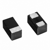
298D226X0010M2T Vishay, 298D226X0010M2T Datasheet

298D226X0010M2T
Specifications of 298D226X0010M2T
Available stocks
Related parts for 298D226X0010M2T
298D226X0010M2T Summary of contents
Page 1
... P [2.4 ± 0.1] 0.126 ± 0.008 A [3.2 ± 0.2] 0.126 ± 0.008 Q [3.2 ± 0.2] ** Please see document “Vishay Material Category Policy” (5-2008)”: www.vishay.com For technical questions, contact Leadframeless Molded AN FEATURES Small sizes include 0603 and 0402 footprint ...
Page 2
... ° 2 125 ° 0.5 15.0 4.0 50.0 0.5 8.0 10.0 50.0 0.9 15.0 2.6 30.0 3.8 40.0 4.0 30.0 (3) 17.6 30.0 For technical questions, contact: tantalum@vishay.com Vishay Sprague M R-Case CODE Voltage Capacitance w Polarity Bar Code Code e EIA Capacitance Voltage Polarity Bar ...
Page 3
... P 298D107X06R3P2T 1.0 K 298D105X0010K2T 1.5 M 298D155X0010M2T 2.2 K 298D225X0010K2T 2.2 M 298D225X0010M2T 3.3 M 298D335X0010M2T 4.7 M 298D475X0010M2T 10 M 298D106X0010M2T 15 M 298D156X0010M2T 22 M 298D226X0010M2T 33 P 298D336X0010P2T 47 P 298D476X0010P2T 1.0 K 298D105X0016K2T 1.0 M 298D105X0016M2T 2.2 M 298D225X0016M2T 4.7 M 298D475X0016M2T 10 R 298D106X0016R2T 4.7 P 298D475X0020P2T 1.0 M 298D105X0025M2T 1.0 R 298D105X0025R2T 4 ...
Page 4
... Capacitors are capable of withstanding peak voltages in the reverse direction equal to the DC rating °C Reverse Voltage the DC rating °C Vishay does not recommend intentional or repetitive application of reverse voltage If capacitors are to be used at temperatures above + 25 °C, the permissible rms ripple current or voltage shall be calculated using the derating factors: Temperature Derating 1 ° ...
Page 5
... Vishay Sprague ENVIRONMENTAL PERFORMANCE CHARACTERISTICS ITEM CONDITION 1000 h application of rated voltage at 85 °C with a 3 series resistance, Life Test °C MIL-STD-202G method 108A At 40 °C/ 500 h, no voltage Humidity Tests applied. MIL-STD-202G method 103B °C/+ 125 °C, 30 min each, Thermal Shock for 5 cycles ...
Page 6
... IMPEDANCE ESR 1000 100 10 10 µ 100 1000 0.1 For technical questions, contact: tantalum@vishay.com 298D Vishay Sprague “M” Case IMPEDANCE ESR 47 µ 100 1000 FREQUENCY, kHz “M” Case IMPEDANCE ESR 4.7 µ 100 1000 FREQUENCY, kHz “ ...
Page 7
... Vishay Sprague TYPICAL CURVES °C, IMPEDANCE AND ESR VS. FREQUENCY “P” CASE 100.0 10.0 1.0 0.1 0 FREQUENCY, kHz “P” CASE 100.0 10.0 1.0 0.1 0 FREQUENCY, kHz www.vishay.com For technical questions, contact: 44 Solid Tantalum Chip Capacitors Leadframeless Molded ICRO AN 1000.0 ...
Page 8
... The most efficient packaging quantities are full reel increments on MAX. a given reel diameter. The quantities shown allow for the sealed 0.9843 [250.0] empty pockets required conformance with EIA-481-1. Reel Camber size and packaging orientation must be specified in the Vishay (T op View) Sprague part number (MIN ...
Page 9
... Vishay Sprague PAPER TAPE AND REEL PACKAGING in inches [millimeters] T Bottom Cover Tape Top Cover Tape 298D CASE TAPE SIZE SIZE 0.033 ± 0.002 0.053 ± 0.002 0.06 ± 0.004 [0.85 ± 0.05] [1.35 ± 0.05] 0.041 ± 0.002 0.071 ± 0.002 0.06 ± ...
Page 10
... S S Sn/Pb Lead (Pb)-free Sn/Pb 217 °C 183 °C 150 °C 100 ° (NOM.) 0.018 [0.45] 0.028 [0.70] 0.031 [0.80] 0.031 [0.80] 0.067 [1.70] For technical questions, contact: tantalum@vishay.com Vishay Sprague MAXIMUM PERMISSIBLE 0.015 0.025 0.045 0.045 0.075 ( MAX. T MAX Lead (Pb)-free ...
Page 11
... Vishay Sprague GUIDE TO APPLICATION 1. A-C Ripple Current: The maximum allowable ripple current shall be determined from the formula --------------- - = rms R ESR where Power dissipation in Watts °C as given in the table in paragraph number 5 (power dissipation The capacitor equivalent series resistance ESR at the specified frequency. ...
Page 12
... Vishay product could result in personal injury or death. Customers using or selling Vishay products not expressly indicated for use in such applications their own risk and agree to fully indemnify and hold Vishay and its distributors harmless from and against any and all claims, liabilities, expenses and damages arising or resulting in connection with such use or sale, including attorneys fees, even if such claim alleges that Vishay or its distributor was negligent regarding the design or manufacture of the part ...


