CSC09B011K00GPA Vishay, CSC09B011K00GPA Datasheet - Page 4
CSC09B011K00GPA
Manufacturer Part Number
CSC09B011K00GPA
Description
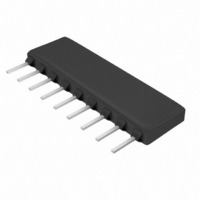
RES NET 1K OHM 9P 8RES SIP
Manufacturer
Vishay
Series
CSCr
Type
Networkr
Specifications of CSC09B011K00GPA
Resistance (ohms)
1K
Number Of Resistors
8
Circuit Type
Bussed
Temperature Coefficient
±100ppm/°C
Tolerance
±2%
Power Per Element
250mW
Number Of Pins
9
Package / Case
9-SIP
Size / Dimension
0.890" L x 0.098" W (22.61mm x 2.49mm)
Height
0.295" (7.49mm)
Mounting Type
Through Hole
Operating Temperature
-55°C ~ 125°C
Technology
Thick Film
Resistance
1kohm
Power Rating
1.45W
Power Rating Per Resistor
1/4W
Tolerance (+ Or -)
2%
Circuit Designator
BUS
Mounting Style
Through Hole
Military Standard
Not Required
Operating Temp Range
-55C to 125C
No. Of Terminals
9
Case Style
Conformal
Failure Rate
Not Required
Termination Style
Pin
Terminal Pitch
2.54
Product Length (mm)
22.61mm
Product Depth (mm)
2.49mm
Product Height (mm)
7.5mm
Lead Free Status / RoHS Status
Contains lead / RoHS non-compliant


Document Number: 31509
Revision: 07-Jun-10
CIRCUIT APPLICATIONS
01 Schematic
03 Schematic
05 Schematic
PERFORMANCE
TEST
Thermal Shock
Short Time Overload
Low Temperature Operation
Moisture Resistance
Resistance to Soldering Heat
Shock
Vibration
Load Life
Terminal Strength
Insulation Resistance
Dielectric Withstanding Voltage
1
1
1
2
2
2
3
3
3
4
1000 h at + 70 °C, rated power applied 1.5 h “ON”, 0.5 h “OFF” for full
Thick Film Resistor Networks, Single-In-Line,
Leads immersed in + 350 °C solder to within 1/16" of body for 3 s
R
R
1
2
n-1
For technical questions, contact:
n-1
12 h at maximum of 20 g's between 10 Hz and 2000 Hz
240 h with humidity ranging from 80 % RH to 98 % RH
No evidence of arcing or damage (200 V
n-1
1000 h period. Derated according to the curve.
n
45 min at full rated working voltage at - 65 °C
n
5 cycles between - 65 °C and + 125 °C
Conformal Coated SIP
n
2.5 x rated working voltage, 5 s
Total of 18 shocks at 100 g's
10 000 MΩ (minimum)
4.5 pound pull for 30 s
CONDITIONS
* “A” profile standard, “B” Profile available.
* “A” Profile standard, “B” Profile available.
The CSCxxx01 single-in-line resistor networks provide the user with
nominally equal resistors, each connected to a common pin
(pin no. 1). Commonly used in the following applications:
• “Wired OR” Pull-up
• Power Gate Pull-up
• MOS/ROM Pull-up/Pull-down
The CSCxxx03 single-in-line resistor networks provide the user with
nominally equal resistors. Each resistor is isolated from all others.
Commonly used in the following applications:
• “Wired OR” Pull-up
• Power Driven Pull-up
• Power Gate Pull-up
• Line Termination
The CSCxxx05 circuits contain series pairs of resistors. Each series
pair is connected between two common lines. The junction of these
resistor pairs is connected to the input terminals. The 05 circuits are
designed for TTL dual-line termination and pulse squaring.
* “A” profile standard, “B” Profile available.
ff2aresistors@vishay.com
RMS
for 1 min)
Dual Terminator
Isolated
Bussed
• Long-Line Impedance Balancing
• LED Current Limiting
• ECL Output Pull-down
• TTL Input Pull-down
• Open Collector Pull-up
• TTL Input Pull-down
• TTL Unused Gate Pull-up
MAX. ΔR (TYPICAL TEST LOTS)
± 0.50 % ΔR
± 0.25 % ΔR
± 0.25 % ΔR
± 1.00 % ΔR
± 0.25 % ΔR
± 0.25 % ΔR
± 0.25 % ΔR
± 1.00 % ΔR
± 0.25 % ΔR
Vishay Dale
-
-
www.vishay.com
CSC
4
Related parts for CSC09B011K00GPA
Image
Part Number
Description
Manufacturer
Datasheet
Request
R

Part Number:
Description:
357-036-542-201 CARDEDGE 36POS DL .156 BLK LOPRO
Manufacturer:
Vishay
Datasheet:
Part Number:
Description:
357-036-542-201 CARDEDGE 36POS DL .156 BLK LOPRO
Manufacturer:
Vishay
Datasheet:
Part Number:
Description:
357-036-542-201 CARDEDGE 36POS DL .156 BLK LOPRO
Manufacturer:
Vishay
Datasheet:
Part Number:
Description:
357-036-542-201 CARDEDGE 36POS DL .156 BLK LOPRO
Manufacturer:
Vishay
Datasheet:
Part Number:
Description:
357-036-542-201 CARDEDGE 36POS DL .156 BLK LOPRO
Manufacturer:
Vishay
Datasheet: