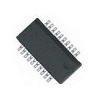
VSSR2401103JTF Vishay, VSSR2401103JTF Datasheet - Page 2

VSSR2401103JTF
Manufacturer Part Number
VSSR2401103JTF
Description
RES NET 10K OHM 24P 23RES QSOP
Manufacturer
Vishay
Series
VSSRr
Type
Networkr
Specifications of VSSR2401103JTF
Resistance (ohms)
10K
Number Of Resistors
23
Circuit Type
Bussed
Temperature Coefficient
±100ppm/°C
Tolerance
±5%
Power Per Element
100mW
Number Of Pins
24
Package / Case
24-LSSOP (0.154", 3.91mm Width)
Size / Dimension
0.341" L x 0.154" W (8.66mm x 3.91mm)
Height
0.054" (1.37mm)
Mounting Type
Surface Mount
Operating Temperature
-55°C ~ 125°C
Technology
Thin Film
Resistance
10kohm
Power Rating
1.4W
Power Rating Per Resistor
1/10W
Tolerance (+ Or -)
5%
Circuit Designator
BUS
Mounting Style
Surface Mount
Military Standard
Not Required
Operating Temp Range
-55C to 125C
No. Of Terminals
24
Case Style
Molded
Failure Rate
Not Required
Termination Style
Gull Wing
Terminal Pitch
0.64
Product Length (mm)
8.66mm
Product Depth (mm)
5.99mm
Product Height (mm)
1.63mm
Product Type
Networks
Operating Temperature Range
- 55 C to + 125 C
Dimensions
3.91 mm W x 8.66 mm L x 1.63 mm H
Lead Spacing
0.64 mm
Body Material
Molded Epoxy
Voltage Rating
50 Volts
Lead Free Status / RoHS Status
Lead free / RoHS Compliant
Lead Free Status / RoHS Status
Lead free / RoHS Compliant, Compliant
VTSR, VSSR, VSOR
Vishay Thin Film
www.vishay.com
22
STANDARD ELECTRICAL SPECIFICATIONS
TEST
Material
Pin/Lead Number
Resistance Range
TCR: Absolute
TCR: Tracking
Tolerance: Absolute
Tolerance: Ratio
Power Rating: Resistor
Power Rating: Package
Stability: Absolute
Stability: Ratio
Voltage Coefficient
Working Voltage
Operating Temperature Range
Storage Temperature Range
Noise
Thermal EMF
Shelf Life Stability: Absolute
Shelf Life Stability: Ratio
DIMENSIONS AND IMPRINTING in inches (millimeters)
MARKING
MODEL
VXXX
VSOR
VSSR
VTSR
DIMENSION
A - 16 PIN
A - 20 PIN
A - 24 PIN
B (Ref.)
C (Ref.)
E (Typ.)
J (Ref.)
W
G
D
H
F
PIN COUNT
(Optional)
XX
16
20
24
Dual-In-Line Resistor, Surface Mount Network
SCHEMATIC
05 or 47
01, 03,
0.206 ± 0.003 (5.23 ± 0.08)
0.256 ± 0.003 (6.50 ± 0.08)
0.306 ± 0.003 (7.77 ± 0.08)
0.173 ± 0.003 (4.39 ± 0.08)
0.252 ± 0.005 (6.40 ± 0.13)
0.043 ± 0.005 (1.09 ± 0.13)
XX
B
For technical questions, contact:
0.015 × 45° (0.38)
Pin #1
0.0256 (0.65)
0.0087 (0.22)
VTSR-xxxx
0.004 (0.10)
0.024 (0.61)
0.005 (0.13)
Molded, 25 mil or 50 mil Pitch,
100 Ω. R is used to designate
A
4 digits are used to express
ohmic values only less than
C
16 = 1.0 W, 20 = 1.2 W, 24 = 1.4 W
± 5 % standard (± 2 % available)
± 1 % standard (check factory)
the decimal position
Part Marking-Model, Pin Count (Optional), Schematic
1 % RESISTANCE
xxxx
RESISTANCE
e.g.: 43R2
- 55 °C to + 125 °C
- 55 °C to + 150 °C
SPECIFICATIONS
5 ppm/V (typical)
Tantalum nitride
XXXX
10 Ω to 47 kΩ
± 100 ppm/°C
100 mW max.
16, 20, 24
< - 35 dB
50 V
Resistance
Value
Code
D
Date
Code
NA
NA
-
-
-
-
-
DC
0.193 ± 0.004 (4.90 ± 0.010)
0.341 ± 0.003 (8.66 ± 0.08)
0.341 ± 0.003 (8.66 ± 0.08)
0.154 ± 0.003 (3.91 ± 0.08)
0.236 ± 0.008 (5.99 ± 0.20)
0.064 ± 0.005 (1.63 ± 0.13)
thinfilm@vishay.com
0.015 × 45° (0.38)
F
VSSR-xxxx
0.025 (0.64)
0.010 (0.25)
0.006 (0.15)
0.025 (0.64)
0.010 (0.25)
G
OR
W
The first 2 digits are significant
figures, the last digit specifies
the number of zeros to follow.
1 %, 2 %, 5 % RESISTANCE
J
H
e.g.: 103 = 10K
RESISTANCE
E
XXX
- 55 °C to + 125 °C
0 °C to + 70 °C
0.390 ± 0.010 (9.91 ± 0.25)
0.152 ± 0.003 (3.86 ± 0.08)
0.236 ± 0.005 (5.99 ± 0.13)
0.064 ± 0.005 (1.63 ± 0.13)
Per E-24 table
Per E-24 table
Per E-96 table
CONDITIONS
At + 70 °C
0.015 × 45° (0.38)
Document Number: 60003
-
-
-
-
-
-
-
-
-
-
-
-
-
-
VSOR-xxxx
0.016 (0.41)
0.050 (1.27)
0.008 (0.20)
0.030 (0.76)
0.008 (0.20)
Revision: 25-Jan-10
NA
NA
DATE CODE
XXXX


