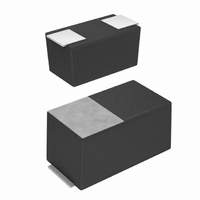
TCM1A225M8R Rohm Semiconductor, TCM1A225M8R Datasheet - Page 3

TCM1A225M8R
Manufacturer Part Number
TCM1A225M8R
Description
CAP TANTALUM 2.2UF 10V 20% SMD
Manufacturer
Rohm Semiconductor
Series
TCr
Type
Moldedr
Datasheet
1.TCM1A475M8R.pdf
(7 pages)
Specifications of TCM1A225M8R
Capacitance
2.2µF
Voltage - Rated
10V
Tolerance
±20%
Esr (equivalent Series Resistance)
13.50 Ohm
Operating Temperature
-55°C ~ 125°C
Mounting Type
Surface Mount
Package / Case
0603 (1608 Metric)
Size / Dimension
0.063" L x 0.033" W (1.60mm x 0.85mm)
Height
0.032" (0.80mm)
Manufacturer Size Code
M
Features
General Purpose
Lead Free Status / RoHS Status
Lead free / RoHS Compliant
Lead Spacing
-
Other names
511-1495-2
Available stocks
Company
Part Number
Manufacturer
Quantity
Price
Part Number:
TCM1A225M8R
Manufacturer:
ROHM/罗姆
Quantity:
20 000
○
TC Series M Case
Operating Temperature
Maximum operating
temperature with no voltage
derating
Rated voltage (VDC)
Category voltage (VDC)
Surge voltage (VDC)
DC Leakage current
Capacitance tolerance
Impedance
Resistance to
Soldering heat
Temperature
cycle
Moisture
resistance
c
Tangent of loss angle
(Df, tan δ)
www.rohm.com
Characteristics
2009 ROHM Co., Ltd. All rights reserved.
Item
Appearance
L.C.
∆C / C
Df (tan δ)
Appearance
L.C.
∆C / C
Df (tan δ)
Appearance
L.C.
∆C / C
Df (tan δ)
2.5
1.6
3.2
TCM0J336
TCM0J336
TCM0J336
Shall be satisfied the voltage on
" Standard list "
Shall be satisfied allowance range.
± 20%
Shall be satisfied the voltage on
" Standard list "
Shall be satisfied the voltage on
" Standard list "
−55 °C to +125 °C
+85 °C
There should be no significant abnormality.
The indications should be clear.
Less than 200% of initial limit
Less than 200% of initial limit
There should be no significant abnormality.
The indications should be clear.
Less than 200% of initial limit
Less than 200% of initial limit
There should be no significant abnormality.
The indications should be clear.
Less than 200% of initial limit
Less than 200% of initial limit
2.5
5.2
4
Others : Within ±20% of initial value.
Others : Within ±20% of initial value.
Others : Within ±20% of initial value.
6.3
4
8
6.3
10
13
: Within ±30% of initial value.
: Within ±30% of initial value.
: Within ±30% of initial value.
16
10
20
Performance
3/6
Test conditions (based on JIS C 5101−1 and JIS C 5101−3)
Voltage reduction when temperature exceeds + 85 °C
at 85 °C
at 125 °C
at 85 °C
As per 4.9 JIS C 5101-1
As per 4.5.1 JIS C 5101-3
Voltage : Rated voltage for 5min
As per 4.7 JIS C 5101-1
As per 4.5.2 JIS C 5101-3
Measuring frequency : 120 ± 12Hz
Measuring voltage
Measuring circuit
As per 4.8 JIS C 5101-1
As per 4.5.3 JIS C 5101-3
Measuring frequency : 120 ± 12Hz
Measuring voltage
Measuring circuit
As per 4.10 JIS C 5101-1
As per 4.5.4 JIS C 5101-3
Measuring frequency : 100 ± 10kHz
Measuring voltage
Measuring circuit
As per 4.14 JIS C 5101-1
As per 4.6 JIS C 5101-3
Dip in the solder bath
After the specimens, leave it at room temperature for
over 24h and then measure the sample.
As per 4.16 JIS C 5101-1
As per 4.10 JIS C 5101-3
Repetition : 5 cycles
(1 cycle : steps 1 to 4) without discontinuation.
After the specimens, leave it at room temperature for
over 24h and then measure the sample.
As per 4.22 JIS C 5101-1
As per 4.12 JIS C 5101-3
After leaving the sample under such atmospheric
condition that the temperature and humidity are
60±2°C and 90 to 95% RH,respectiveiy, for 500±12h
leave it at room
temperature for over 24h and then measure the
sample.
Solder temp
Duration
Repetition
1
2
3
4
Room temp.
Room temp.
−55 3°C
125 2°C
Temp.
+ −
+ −
: 0.5Vrms +1.5.DC
: DC Equivalent series circuit
: 0.5Vrms +1.5.DC
: DC Equivalent series circuit
: 0.5Vrms or less
: DC Equivalent series circuit
: 260 ± 5 °C
: 5 ± 0.5s
: 1
3min.or less
3min.or less
30±3min.
30±3min.
Time
2009.11 - Rev.G
Data Sheet


