MAL212313151E3 Vishay, MAL212313151E3 Datasheet - Page 11
MAL212313151E3
Manufacturer Part Number
MAL212313151E3
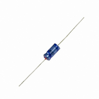
Description
CAP 6.3V 150UF SOLID ELECT AXIAL
Manufacturer
Vishay
Series
SAL-A 123r
Datasheet
1.MAL212310108E3.pdf
(12 pages)
Specifications of MAL212313151E3
Capacitance
150µF
Voltage Rating
6.3V
Tolerance
±20%
Lifetime @ Temp.
20000 Hrs @ 125°C
Operating Temperature
-55°C ~ 125°C
Features
General Purpose
Ripple Current
160mA
Esr (equivalent Series Resistance)
1.500 Ohm
Impedance
1 Ohm
Mounting Type
Through Hole
Package / Case
Axial, Can
Size / Dimension
0.299" Dia x 0.803" L (7.60mm x 20.40mm)
Lead Free Status / RoHS Status
Contains lead / RoHS non-compliant
Height
-
Lead Spacing
-
Surface Mount Land Size
-
Other names
2222 123 13151
222212313151
4266PHTB
MAL212313151
222212313151
4266PHTB
MAL212313151


ADDITIONAL TESTS AND REQUIREMENTS FOR EPOXY-FILLED VERSIONS SAL-AG
2281 123 8.... Form BA ± 10 %, level S, lead (Pb)-free
2222 123 8.... Form BA ± 10 %, level S, non lead (Pb)-free
Table 4
Document Number: 28355
Revision: 23-Jun-08
TEST PROCEDURES AND REQUIREMENTS
Severe vibration tests in accordance with “IEC 60068-2-6” and “MIL STD-202”, method 204, letter E, with the following details and
additions
Method of mounting:
severity 1
severity 2
severity 1 and 2
Direction and duration of motion:
severity 1
severity 2
Functioning:
severity 1
severity 2
Typical capability
Severe shock tests in accordance with “IEC 60068-2-27” and “MIL STD-202”, method 213, letter F, with the following details and
additions:
Method of mounting
Pulse shape:
severity 1
severity 2
severity 3
Direction and number of shocks:
severity 1 and 2
severity 3
Functioning
TEST
clamping both body and leads
frequency range temperature 10 to 3000 Hz; 20 to 25 °C
frequency range temperature 50 to 2000 Hz; 125 °C
vibration amplitude: 50 g or 3.5 mm, whichever is less
1 octave/minute; 3 directions (mutually perpendicular);
20 sweeps per direction (total 60 sweeps or 18 hours)
1 octave/minute; 2 directions (longitudinal and
transversal); 3 sweeps per direction
(total 6 sweeps or 1 hour)
rated voltage applied
no voltage applied
> 80 g at 10 to 3000 Hz (also at 125 °C)
clamping both body and leads
half-sine or sawtooth
1500 g; 0.5 ms (“MIL STD-202”, method 213, letter F)
3000 g; 0.2 ms
10 000 g; 0.1 ms
3 successive shocks in each direction of 3 mutually
perpendicular axes (total 18 shocks)
1 shock in any direction
rated voltage applied
For technical questions, contact: aluminumcaps2@vishay.com
Aluminum Capacitors
Solid Axial
PROCEDURE
ΔC/C: ± 10 %
tan δ ≤ 1.2 x stated limit
Z ≤ 1.4 x stated limit
DC leakage current: ≤ stated limit
no intermittent contacts
no indication of breakdown
no open circuiting
no evidence of mechanical damage
ΔC/C: ± 10 %
tan δ ≤ 1.2 x stated limit
Z ≤ 1.4 x stated limit
DC leakage current: ≤ stated limit
no intermittent contacts
no indication of breakdown
no open circuiting
no evidence of mechanical damage
Vishay BCcomponents
REQUIREMENTS
123 SAL-A
www.vishay.com
261
Related parts for MAL212313151E3
Image
Part Number
Description
Manufacturer
Datasheet
Request
R

Part Number:
Description:
357-036-542-201 CARDEDGE 36POS DL .156 BLK LOPRO
Manufacturer:
Vishay
Datasheet:
Part Number:
Description:
357-036-542-201 CARDEDGE 36POS DL .156 BLK LOPRO
Manufacturer:
Vishay
Datasheet:
Part Number:
Description:
357-036-542-201 CARDEDGE 36POS DL .156 BLK LOPRO
Manufacturer:
Vishay
Datasheet:
Part Number:
Description:
357-036-542-201 CARDEDGE 36POS DL .156 BLK LOPRO
Manufacturer:
Vishay
Datasheet:
Part Number:
Description:
357-036-542-201 CARDEDGE 36POS DL .156 BLK LOPRO
Manufacturer:
Vishay
Datasheet:
Part Number:
Description:
357-036-542-201 CARDEDGE 36POS DL .156 BLK LOPRO
Manufacturer:
Vishay
Datasheet:
Part Number:
Description:
357-036-542-201 CARDEDGE 36POS DL .156 BLK LOPRO
Manufacturer:
Vishay
Datasheet:
Part Number:
Description:
357-036-542-201 CARDEDGE 36POS DL .156 BLK LOPRO
Manufacturer:
Vishay
Datasheet:
Part Number:
Description:
357-036-542-201 CARDEDGE 36POS DL .156 BLK LOPRO
Manufacturer:
Vishay
Datasheet:
Part Number:
Description:
357-036-542-201 CARDEDGE 36POS DL .156 BLK LOPRO
Manufacturer:
Vishay
Datasheet:
Part Number:
Description:
357-036-542-201 CARDEDGE 36POS DL .156 BLK LOPRO
Manufacturer:
Vishay
Datasheet:
Part Number:
Description:
357-036-542-201 CARDEDGE 36POS DL .156 BLK LOPRO
Manufacturer:
Vishay
Datasheet:
Part Number:
Description:
357-036-542-201 CARDEDGE 36POS DL .156 BLK LOPRO
Manufacturer:
Vishay
Datasheet:
Part Number:
Description:
357-036-542-201 CARDEDGE 36POS DL .156 BLK LOPRO
Manufacturer:
Vishay
Datasheet:
Part Number:
Description:
357-036-542-201 CARDEDGE 36POS DL .156 BLK LOPRO
Manufacturer:
Vishay
Datasheet: