T491B225K025AT Kemet, T491B225K025AT Datasheet - Page 20
T491B225K025AT
Manufacturer Part Number
T491B225K025AT
Description
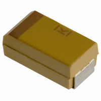
CAPACITOR TANT 2.2UF 25V 10% SMD
Manufacturer
Kemet
Series
T491r
Type
Moldedr
Datasheet
1.T491A335K016AH.pdf
(24 pages)
Specifications of T491B225K025AT
Capacitance
2.2µF
Voltage - Rated
25V
Tolerance
±10%
Esr (equivalent Series Resistance)
4.500 Ohm
Operating Temperature
-55°C ~ 125°C
Mounting Type
Surface Mount
Package / Case
1210 (3528 Metric)
Size / Dimension
0.138" L x 0.110" W (3.50mm x 2.80mm)
Height
0.075" (1.90mm)
Manufacturer Size Code
B
Features
General Purpose
Voltage Rating
25 Volts
Esr
4.5 Ohms
Operating Temperature Range
- 55 C to + 125 C
Mfr Case Code
B Case
Dimensions
2.8 mm W x 3.5 mm L x 1.9 mm H
Leakage Current
0.6 uAmps
Product
Tantalum Solid Standard Grade - Other Various
Termination Style
SMD/SMT
Capacitance Tolerance
± 10%
Capacitor Case Style
3528-21
Msl
MSL 1 - Unlimited
Rohs Compliant
Yes
Tolerance (+ Or -)
10%
Voltage
25VDC
Mounting Style
Surface Mount
Polarity
Polar
Construction
SMT Chip
Case Style
Molded
Case Code
B
Lead Spacing (nom)
Not Requiredmm
Df
6%
Dcl
0.6uA
Seal
Not Required
Insulation
Not Required
Failure Rate
Not Required
Wire Form
Not Required
Product Length (mm)
3.5mm
Product Height (mm)
1.9mm
Product Depth (mm)
2.8mm
Product Diameter (mm)
Not Requiredmm
Seated Plane Height
Not Requiredmm
Length W/weld (max)
Not Requiredmm
Operating Temp Range
-55C to 125C
Lead Free Status / RoHS Status
Lead free / RoHS Compliant
Lead Spacing
-
Lead Free Status / Rohs Status
Lead free / RoHS Compliant
Other names
399-3715-2
Available stocks
Company
Part Number
Manufacturer
Quantity
Price
Company:

Part Number:
T491B225K025AT
Manufacturer:
KEMET
Quantity:
6 000
Company:
Part Number:
T491B225K025AT
Manufacturer:
KEMET
Quantity:
26 000


Standard MnO
Packaging Information Performance Notes
1. Cover Tape Break Force: 1.0 Kg Minimum.
2. Cover Tape Peel Strength: The total peel strength of the cover tape from the carrier tape shall be:
3. Labeling: Bar code labeling (standard or custom) shall be on the side of the reel opposite the sprocket holes. Refer to EIA-556 and EIA-624.
Figure 3 – Maximum Component Rotation
Figure 4 – Maximum Lateral Movement
Figure 5 – Bending Radius
© KEMET Electronics Corporation • P.O. Box 5928 • Greenville, SC 29606 (864) 963-6300 • www.kemet.com
The direction of the pull shall be opposite the direction of the carrier tape travel. The pull angle of the carrier tape shall be 165° to 180° from the plane of the
carrier tape. During peeling, the carrier and/or cover tape shall be pulled at a velocity of 300±10 mm/minute.
8mm & 12mm Tape
Bo
Embossed
Carrier
12mm & 16mm
Tape Width
2
8mm
Tantalum Surface Mount Capacitors – T491 Industrial Grade MnO
Ao
R
T
°
0.5 mm maximum
0.5 mm maximum
Bending
Radius
Maximum Component Rotation
8,12
Tape
Width (mm)
16-200
Typical Component Centerline
Typical Pocket Centerline
Punched
Carrier
0.1 Newton to 1.0 Newton (10gf to 100gf)
0.1 Newton to 1.3 Newton (10gf to 130gf)
Top View
R
16mm Tape
Maximum
Peel Strength
Rotation (
20
10
1.0 mm maximum
1.0 mm maximum
T
°
)
s
2
°
Series
Maximum Component Rotation
8,12
72-200
Tape
Width (mm)
16-56
Side View
Maximum
Rotation (
10
20
5
S
°
T2005-1 • 1/17/2011
)
20 20
Related parts for T491B225K025AT
Image
Part Number
Description
Manufacturer
Datasheet
Request
R

Part Number:
Description:
CAP, KEMET #F601BL105K250C
Manufacturer:
Kemet
Datasheet:
Part Number:
Description:
Manufacturer:
Kemet
Datasheet:
Part Number:
Description:
Manufacturer:
Kemet
Datasheet: