C1005C0G1H121J TDK Corporation, C1005C0G1H121J Datasheet - Page 56
C1005C0G1H121J
Manufacturer Part Number
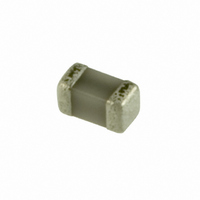
C1005C0G1H121J
Description
CAP CER 120PF 50V C0G 5% 0402
Manufacturer
TDK Corporation
Series
Cr
Datasheets
1.C1005X7R1E103K.pdf
(62 pages)
2.C1005X7R1E103K.pdf
(1 pages)
3.C1005C0G1H121J.pdf
(1 pages)
4.C1005C0G1H121J.pdf
(31 pages)
Specifications of C1005C0G1H121J
Capacitance
120pF
Package / Case
0402 (1005 Metric)
Voltage - Rated
50V
Tolerance
±5%
Temperature Coefficient
C0G, NP0
Mounting Type
Surface Mount, MLCC
Operating Temperature
-55°C ~ 125°C
Features
Low ESR
Applications
General Purpose
Size / Dimension
0.039" L x 0.020" W (1.00mm x 0.50mm)
Thickness
0.50mm
Tolerance (+ Or -)
5%
Voltage
50VDC
Temp Coeff (dielectric)
C0G
Operating Temp Range
-55C to 125C
Mounting Style
Surface Mount
Construction
SMT Chip
Case Style
Ceramic Chip
Failure Rate
Not Required
Wire Form
Not Required
Product Length (mm)
1mm
Product Depth (mm)
0.5mm
Product Height (mm)
0.5mm
Product Diameter (mm)
Not Requiredmm
Dielectric Characteristic
C0G / NP0
Capacitance Tolerance
± 5%
Voltage Rating
50VDC
Capacitor Case Style
0402
No. Of Pins
2
Capacitor Mounting
SMD
Rohs Compliant
Yes
Lead Free Status / RoHS Status
Lead free / RoHS Compliant
Ratings
-
Lead Spacing
-
Lead Free Status / RoHS Status
Compliant, Lead free / RoHS Compliant
Other names
445-1248-2
C1005C0G1H121J
C1005C0G1H121JT
C1005C0G1H121JT
C1005COG1H121J
C1005C0G1H121J
C1005C0G1H121JT
C1005C0G1H121JT
C1005COG1H121J


• All specifications are subject to change without notice. Please read the precautions before using the product.
US Catalog // C Series — General Application // Version A11
No.
15
General
Specifications
Item
Moisture Resistance (Steady State)
External
appearance
Capacitance
Q
(Class 1)
D.F.
(Class 2)
Insulation
Resistance
Performance
No mechanical damage.
Characteristics
X5R: 200% of initial spec. max.
X7R: 200% of initial spec. max
Y5V: 150% of initial spec. max
1,000MΩ or 50MΩ•μF min.
(As for the capacitors of rated voltage
16, 10 and 6.3V DC, 1,000 MΩ or
10MΩ•μF min.,) whichever smaller.
Characteristics
Class 1
Class 2
Rated
Capacitance
C ≥ 30pF
10pF ≤ C < 30pF
C <10pF
C0G
X5R
X7R
Y5V
C : Rated capacitance (pF)
Change from the
value before test
±5% or ±0.5pF,
whichever larger.
± 25 %
± 25 %
± 30 %
Q
350 min.
275+5/2×C min.
200+10×C min.
C Series — General Application
Test or Inspection Method
Reflow solder the capacitor on P.C. board (shown in
Appendix 1a or Appendix 1b) before testing.
Leave at temperature 40±2ºC, 90 to 95%RH for 500
+24,0h.
Leave the capacitor in ambient conditions for 6 to 24h
(Class 1) or 24±2h (Class 2) before measurement.
Related parts for C1005C0G1H121J
Image
Part Number
Description
Manufacturer
Datasheet
Request
R

Part Number:
Description:
TDK DC to DC Converters, DC to AC Inverters
Manufacturer:
TDK Corporation
Datasheet:
Part Number:
Description:
TDK DC to DC Converters, DC to AC Inverters
Manufacturer:
TDK Corporation
Datasheet: