ECJ-2VB1H103K Panasonic - ECG, ECJ-2VB1H103K Datasheet - Page 2
ECJ-2VB1H103K
Manufacturer Part Number
ECJ-2VB1H103K
Description
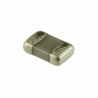
CAP 10000PF 50V CERM CHIP 0805
Manufacturer
Panasonic - ECG
Series
ECJr
Datasheets
1.ECJ-RVB1H332M.pdf
(6 pages)
2.ECJ-RVB1H332M.pdf
(2 pages)
3.ECJ-RVB1H332M.pdf
(1 pages)
4.ECJ-RVB1H332M.pdf
(3 pages)
5.ECJ-0EB1H102K.pdf
(12 pages)
Specifications of ECJ-2VB1H103K
Capacitance
10000pF
Voltage - Rated
50V
Tolerance
±10%
Temperature Coefficient
X7R
Mounting Type
Surface Mount, MLCC
Operating Temperature
-55°C ~ 125°C
Features
Low ESR
Applications
General Purpose
Package / Case
0805 (2012 Metric)
Size / Dimension
0.079" L x 0.049" W (2.00mm x 1.25mm)
Thickness
0.60mm
Lead Free Status / RoHS Status
Lead free / RoHS Compliant
Ratings
-
Lead Spacing
-
Other names
ECJ-2YB1H103K
ECJ2VB1H103K
ECJ2YB1H103K
ECU-V1H103KBG
ECUV1H103KBG
PCC103BNTR
ECJ2VB1H103K
ECJ2YB1H103K
ECU-V1H103KBG
ECUV1H103KBG
PCC103BNTR
Available stocks
Company
Part Number
Manufacturer
Quantity
Price
Company:

Part Number:
ECJ-2VB1H103K
Manufacturer:
PANASONIC
Quantity:
240 000


Design and specifi cations are each subject to change without notice. Ask factory for the current technical specifi cations before purchase and/or use.
Should a safety concern arise regarding this product, please be sure to contact us immediately.
1.7 Capacitance Aging
1.8 Piezoelectricity
Under Ordinary Temperature
(1) If capacitance change caused by the applied voltage
(2) DC voltage characteristics demonstrate that even
The ceramic dielectrics of the Capacitors (Class 2) have
capacitance aging. Accordingly, when the Capacitors
are used for circuits which require a narrow allowable
capacitance range, such as time constant circuits, pay
special attention to capacitance aging before use.
Dielectrics used for the Capacitors (Class 2) may
cause the following Piezoelectricity (or Electrostriction).
(1) If the signal of a specifi c frequency is applied to
(2) Vibration or impact applied to the Capacitors may
(3) If a “whining sound” is generated it does not
0
In addition, changing the materials of the Capacitors
As a measure to prevent this phenomenon, changing
is within the allowable range, or if its application allows
unlimited capacitance change.
if the applied voltage is under the rated voltage,
the capacitance change rate increases with higher
voltage (Capacitance down). Accordingly, when the
Capacitors are used for circuits with a narrow allowable
capacitance range such as time constant circuits, we
recommend applying a lower voltage after taking
capacitance aging and the above into account.
the Capacitors, electric and acoustic noise may be
generated by resonating the characteristic frequen-
cy, which is determined by the dimensions of the
Capacitor.
As a measure to prevent this phenomenon, changing
the size of the Capacitor is effective in changing its
resonance frequency.
to the Low - loss type, which has no (or less)
piezoelectricity, or to use Class 1 dielectrics which
have no (or less) piezoelectricity.
cause noise because mechanical force is converted
to electrical signals (Especially to circuitry around
an amplifi er unit).
the materials of the Capacitor to the Low-loss type,
which has no (or less) piezoelectricity, or to Class1 is
also available.
indicate a problem with product performance
and reliability, however, check if this undesirable
phenomenon generates noise in your application.
To prevent this phenomenon, changing the Capacitor’s
characteristics, such as size and shape, as
shown in (1) & (2) above can be effective.
In addition, changing the mounting direction
Time (h)
Capacitance change - DC voltage
0
log T
0
DC voltage (V)
Before and After Heat treatment
0
Heat Treatment
Time (h)
log T
– EC49 –
2. Design of Printed Circuit Board
Recommended land dimensions (Ex.)
<
✽1 The following value is applied as a dimensional tolerance :
<2Array type, 4 Array type>
2 Array
4 Array
4 Array
2.1 Selection of Printed Circuit Board
2.2 Design of Land Pattern
0402
0504
0805
1206
Size
0201
0402
0603
0805
1206
0508
0612
1210
Size
When the Capacitors are mounted and soldered on
an “Alumina Substrate”, the substrate infl uences the
Capacitors’ reliability against “Temperature Cycles”
and “Heat shock” due to the difference in the thermal
expansion coeffi cient between them. Confi rm that the
actual board used does not deteriorate the characteristics
of the Capacitors.
(1) Recommended land dimensions are shown below.
High Capacitance, For General Electronic
Equipment, Low Profi leType, Wide-width Type,
100V·200V series, 630V series, High-Q capacitors
+0.15/-0.05 mm (L, W and T).
LAND
✽1
of the Capacitors may be effective in getting the
resonance under control with other equipment such as
printed circuit boards. Attaching the Capacitors to
the printed circuit board by an adhesive may also
be effective.
Use the proper amount of solder in order to prevent
cracking. Using too much solder places excessive
stress on the Capacitors.
c
1.37 1.0
3.2
2.0 1.25 0.85 0.55 to 0.75 0.5 to 0.6 0.2 to 0.3 0.4 to 0.6
b
L
Component
Dimensions
Component Dimensions
1.25
0.6
2.0
3.2
3.2
1.0
1.0
1.6
1.6
L
P
1.6 0.85 0.9 to 1.1 0.7 to 0.9 0.35 to 0.45 0.7 to 0.9
W
a
1.25 0.6 to 1.25 0.8 to 1.2 0.8 to 1.0 0.8 to 1.0
0.3
0.5
0.5
3.2
0.8
1.6
2.5
2.0
Multilayer Ceramic Capacitors
W
0.6
0.8 0.3 to 0.6 0.4 to 0.7 0.46 to 0.56 0.71 to 0.91
T
LAND
0.85 to 2.5 1.8 to 2.2 1.0 to 1.2 1.8 to 2.3
0.6 to 1.6 1.8 to 2.2 1.0 to 1.2 1.0 to 1.3
0.45 to 0.8 0.8 to 1.0 0.6 to 0.8 0.6 to 0.8
SMD
0.3 to 0.4 0.45 to 0.55 0.3 to 0.4 0.54 to 0.74
0.85
0.85
0.3
0.5
0.5
T
a
Solder resist
SMD
0.5 to 0.6 0.4 to 0.5 0.5 to 0.6
0.2 to 0.3 0.25 to 0.3 0.2 to 0.3
0.4 to 0.5 0.4 to 0.5 0.4 to 0.5
0.5 to 0.7 0.5 to 0.6 1.4 to 1.9
0.8 to 1.0 0.6 to 0.7 2.5 to 3.0
a
b
P/2
b
b
c
c
P
a
00 Sep. 2008
LAND
Unit (mm)
Unit (mm)
c
P
>
Related parts for ECJ-2VB1H103K
Image
Part Number
Description
Manufacturer
Datasheet
Request
R

Part Number:
Description:
CAP ARRAY 22PF 50V NP0 0504
Manufacturer:
Panasonic - ECG
Datasheet:
Part Number:
Description:
CAP ARRAY 10PF 50V NP0 0504
Manufacturer:
Panasonic - ECG
Datasheet:
Part Number:
Description:
CAP ARRAY 100PF 50V NP0 0504
Manufacturer:
Panasonic - ECG
Datasheet:
Part Number:
Description:
CAP ARRAY 47PF 50V NP0 0504
Manufacturer:
Panasonic - ECG
Datasheet:
Part Number:
Description:
CAP ARRAY 2.2UF 6.3V X5R 0504
Manufacturer:
Panasonic - ECG
Datasheet:
Part Number:
Description:
CAP ARRAY .1UF 10V X5R 0504
Manufacturer:
Panasonic - ECG
Datasheet:
Part Number:
Description:
CAP ARRAY 1UF 6.3V X5R 0504
Manufacturer:
Panasonic - ECG
Datasheet:
Part Number:
Description:
CAP ARRAY 1UF 6.3V X5R 0504
Manufacturer:
Panasonic - ECG
Datasheet:
Part Number:
Description:
CAP ARRAY 1UF 10V X5R 0504
Manufacturer:
Panasonic - ECG
Datasheet:
Part Number:
Description:
CAP ARRAY 1UF 10V X5R 0504
Manufacturer:
Panasonic - ECG
Datasheet:


Part Number:
Description:
MICROPHONE OMNI 6X2.2MM W/CAP
Manufacturer:
Panasonic - ECG
Datasheet:

Part Number:
Description:
CAP .01UF 100V PEN FILM 1210 5%
Manufacturer:
Panasonic - ECG
Datasheet:

Part Number:
Description:
FILTER LINE 23.3MH 2A
Manufacturer:
Panasonic - ECG
Datasheet:

Part Number:
Description:
SAW FILTER PCS 1960 MHZ 50/150
Manufacturer:
Panasonic - ECG
Datasheet: