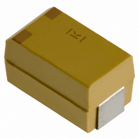
T530X477M006ATE006 Kemet, T530X477M006ATE006 Datasheet - Page 7

T530X477M006ATE006
Manufacturer Part Number
T530X477M006ATE006
Description
CAPACITOR TANT 470UF 6.3V 20%SMD
Manufacturer
Kemet
Series
T530r
Type
Moldedr
Specifications of T530X477M006ATE006
Capacitance
470µF
Voltage - Rated
6.3V
Tolerance
±20%
Esr (equivalent Series Resistance)
6.0 mOhm
Operating Temperature
-55°C ~ 125°C
Mounting Type
Surface Mount
Package / Case
2917 (7343 Metric)
Size / Dimension
0.287" L x 0.169" W (7.30mm x 4.30mm)
Height
0.157" (4.00mm)
Manufacturer Size Code
X
Features
Polymer
Voltage Rating
6.3 Volts
Esr
6 mOhms
Operating Temperature Range
- 55 C to + 125 C
Dimensions
4.3 mm W x 7.3 mm L x 4 mm H
Dissipation Factor Df
8
Leakage Current
296 uAmps
Product
Tantalum Organic Polymer Standard Grade
Ripple Current
6.7 mAmps
Termination Style
SMD/SMT
Capacitance Tolerance
± 20%
Capacitor Case Style
2917
Msl
MSL 3 - 168 Hours
Rohs Compliant
Yes
Lead Free Status / RoHS Status
Lead free / RoHS Compliant
Lead Spacing
-
Lead Free Status / Rohs Status
Lead free / RoHS Compliant
Other names
399-4136-2
Available stocks
Company
Part Number
Manufacturer
Quantity
Price
Company:
Part Number:
T530X477M006ATE006
Manufacturer:
KEMET
Quantity:
26 000
KEMET Organic Capacitor (KO-CAP) – T530 High Capacitance/125°C Rated Polymer Tantalum
Derating Guidelines
V
Ripple Current/Ripple Voltage
Permissible AC ripple voltage and current are related to equivalent series resistance (ESR) and the power dissipation capabilities of the
device. Permissible AC ripple voltage which may be applied is limited by two criteria:
The maximum power dissipation by case size can be determined using the below table. The maximum power dissipation rating stated
in the table above must be reduced with increasing environmental operating temperatures. Refer to the below table for temperature
compensation requirements.
© KEMET Electronics Corporation • P.O. Box 5928 • Greenville, SC 29606 (864) 963-6300 • www.kemet.com
r
2.5V ≤ V
2.5V ≤ V
= Rated Voltage
a. The positive peak AC voltage plus the DC bias voltage, if any, must not exceed the DC voltage rating of the capacitor.
b. The negative peak AC voltage, in combination with bias voltage, if any, must not exceed the allowable limits specified for reverse
voltage.
T520/525T
T520/525B
T520/525D
Voltage
Rating
V
V
KEMET
T520W
T520M
T520U
T520C
T530D
T520A
T520L
T520V
T520Y
T520X
T528Z
T530Y
T530X
r
r
= 16V
= 16V
r
r
≤ 10V
≤ 10V
Case Code
Steady State Voltage
Max Recommended
7343-40
7343-43
7343-40
3538-21
3528-19
6032-28
7343-20
7343-31
7343-17
7343-31
7443-43
3528-12
3528-15
3216-18
6032-15
6032-15
EIA
90% of V
80% of V
60% of V
54% of V
r
r
r
r
Maximum Power Dissipation (Pmax)
mWatts @ 45°C w/+30°C Rise
105°C to 125°C
-55°C to 105°C
Transient Voltage (1ms - 1µs)
Max Recommended
105
120
127
135
150
165
180
187
225
241
247
325
255
263
270
112
67% of V
67% of V
V
V
r
r
r
r
T= Environmental Temperature
Using the P max of the device, the maximum allowable rms
ripple current or voltage may be determined.
I(max) = √P max/R
E(max) = √P max * R
I = rms ripple current (amperes)
E = rms ripple voltage (volts)
Pmax = maximum power dissipation(watts)
R = ESR at specified frequency (ohms)
≤45°C
1.00
100%
95%
90%
85%
80%
75%
70%
65%
60%
55%
50%
Temperature Compenstion Multipliers
-55
for Maximum Power Dissipation
45°C < T ≤ 85°C
Maximum Transient Voltage
Recommended Application Voltage V
Recommended Application Voltage V
0.70
25
Temperature (ºC)
45
T2019-1 • 1/10/2011
r
r
85
≤ 10V
> 10V
85°C < T ≤ 105°C
0.25
105
125
67%
60%
54%
7 7


