12065C823KAT2A AVX Corporation, 12065C823KAT2A Datasheet - Page 2
12065C823KAT2A
Manufacturer Part Number
12065C823KAT2A
Description
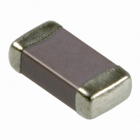
CAP CERM .082UF 10% 50V X7R 1206
Manufacturer
AVX Corporation
Series
1206r
Datasheet
1.0603YC104KAT2A.pdf
(4 pages)
Specifications of 12065C823KAT2A
Capacitance
0.082µF
Tolerance
±10%
Package / Case
1206 (3216 Metric)
Voltage - Rated
50V
Temperature Coefficient
X7R
Mounting Type
Surface Mount, MLCC
Operating Temperature
-55°C ~ 125°C
Applications
General Purpose
Size / Dimension
0.126" L x 0.063" W (3.20mm x 1.60mm)
Thickness
0.94mm Max
Voltage Rating
50 Volts
Operating Temperature Range
- 55 C to + 125 C
Temperature Coefficient / Code
X7R
Product
General Type MLCCs
Dimensions
1.6 mm W x 3.2 mm L x 0.940 mm H
Dissipation Factor Df
2.5
Termination Style
SMD/SMT
Lead Free Status / RoHS Status
Lead free / RoHS Compliant
Features
-
Ratings
-
Lead Spacing
-
Lead Free Status / Rohs Status
Lead free / RoHS Compliant
Other names
478-1555-2


X7R Dielectric
Specifications and Test Methods
Resistance to
Resistance to
Operating Temperature Range
Solder Heat
Load Life
Humidity
Stresses
Thermal
Flexure
Shock
Load
Insulation Resistance
Dielectric Strength
Dissipation Factor
Parameter/Test
Capacitance
Solderability
Capacitance
Capacitance
Capacitance
Capacitance
Capacitance
Appearance
Appearance
Appearance
Appearance
Appearance
Resistance
Resistance
Resistance
Resistance
Resistance
Dissipation
Dissipation
Dissipation
Dissipation
Dissipation
Insulation
Insulation
Insulation
Insulation
Insulation
Dielectric
Dielectric
Dielectric
Dielectric
Variation
Variation
Strength
Variation
Strength
Variation
Strength
Variation
Strength
Factor
Factor
Factor
Factor
Factor
No defects, <25% leaching of either end terminal
≥ 95% of each terminal should be covered
No breakdown or visual defects
≥ Initial Value x 0.3 (See Above)
≥ Initial Value x 0.3 (See Above)
Meets Initial Values (As Above)
Meets Initial Values (As Above)
Meets Initial Values (As Above)
Meets Initial Values (As Above)
≤ Initial Value x 2.0 (See Above)
Meets Initial Values (As Above)
≤ Initial Value x 2.0 (See Above)
Meets Initial Values (As Above)
Meets Initial Values (As Above)
Meets Initial Values (As Above)
Meets Initial Values (As Above)
100,000MΩ or 1000MΩ - μF,
≤ 2.5% for ≥ 50V DC rating
≤ 5.0% for ≤ 10V DC rating
X7R Specification Limits
Within specified tolerance
≤ 3.0% for 25V DC rating
≤ 3.5% for 16V DC rating
≥ Initial Value x 0.3
No visual defects
-55ºC to +125ºC
whichever is less
with fresh solder
No visual defects
No visual defects
No defects
≤ ±12.5%
≤ ±12.5%
≤ ±12%
≤ ±7.5%
≤ ±7.5%
1-5 seconds, w/charge and discharge current
seconds. Store at room temperature for 24 ± 2
Charge device with 1.5 rated voltage (≤ 10V) in
Charge device with 300% of rated voltage for
hours before measuring electrical properties.
Dip device in eutectic solder at 260ºC for 60
Step 1: -55ºC ± 2º
Step 2: Room Temp
Step 3: +125ºC ± 2º
Step 4: Room Temp
Repeat for 5 cycles and measure after
24 ± 2 hours at room temperature
Dip device in eutectic solder at 230 ± 5ºC
85% ± 5% relative humidity for 1000 hours
Store in a test chamber set at 85ºC ± 2ºC/
Note: Charge device with 150% of rated
Remove from test chamber and stabilize
Remove from chamber and stabilize at
120 ± 5 secs @ room temp/humidity
at room temperature for 24 ± 2 hours
Charge device with rated voltage for
For Cap > 10 μF, 0.5Vrms @ 120Hz
(+48, -0) with rated voltage applied.
room temperature and humidity for
test chamber set at 125ºC ± 2ºC
24 ± 2 hours before measuring.
Temperature Cycle Chamber
voltage for 500V devices.
Measuring Conditions
for 1000 hours (+48, -0)
Voltage: 1.0Vrms ± .2V
Test Time: 30 seconds
limited to 50 mA (max)
Freq.: 1.0 kHz ± 10%
for 5.0 ± 0.5 seconds
before measuring.
Deflection: 2mm
90 mm
1mm/sec
30 ± 3 minutes
≤ 3 minutes
30 ± 3 minutes
≤ 3 minutes
17
Related parts for 12065C823KAT2A
Image
Part Number
Description
Manufacturer
Datasheet
Request
R

Part Number:
Description:
Manufacturer:
AVX Corporation
Datasheet:
Part Number:
Description:
Manufacturer:
AVX Corporation
Datasheet:
Part Number:
Description:
Manufacturer:
AVX Corporation
Datasheet:
Part Number:
Description:
Manufacturer:
AVX Corporation
Datasheet:
Part Number:
Description:
Manufacturer:
AVX Corporation
Datasheet: