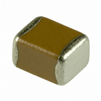
C3225X7R2A474K TDK Corporation, C3225X7R2A474K Datasheet - Page 3

C3225X7R2A474K
Manufacturer Part Number
C3225X7R2A474K
Description
CAP CER .47UF 100V X7R 10% 1210
Manufacturer
TDK Corporation
Series
Cr
Datasheets
1.C1005X7R1E103K.pdf
(1 pages)
2.C1608X7R2A102K.pdf
(26 pages)
3.C3216X7R1E155K.pdf
(17 pages)
Specifications of C3225X7R2A474K
Capacitance
0.47µF
Voltage - Rated
100V
Tolerance
±10%
Temperature Coefficient
X7R
Mounting Type
Surface Mount, MLCC
Operating Temperature
-55°C ~ 125°C
Features
Low ESR
Applications
General Purpose
Package / Case
1210 (3225 Metric)
Size / Dimension
0.126" L x 0.098" W (3.20mm x 2.50mm)
Thickness
2.00mm
Dielectric Characteristic
X7R
Capacitance Tolerance
± 10%
Voltage Rating
100VDC
Capacitor Case Style
1210
No. Of Pins
2
Capacitor Mounting
SMD
Rohs Compliant
Yes
Lead Free Status / RoHS Status
Lead free / RoHS Compliant
Ratings
-
Lead Spacing
-
Other names
445-2293-2
C3225X7R2A474KT
C3225X7R2A474KT
Available stocks
Company
Part Number
Manufacturer
Quantity
Price
Company:
Part Number:
C3225X7R2A474KT
Manufacturer:
TDK
Quantity:
13 523
Part Number:
C3225X7R2A474KT0L0U
Manufacturer:
TDK/东电化
Quantity:
20 000
• All specifications are subject to change without notice. Please read the precautions before using the product.
Features
Dimensions L x W (mm)
Series Name
Temperature Characteristic
Rated Voltage (DC)
Case Code
C1005
C1608
C2012
C3216
C3225
C4532
C5750
Temperature
Characteristics
C0G
X7R
X7S
Voltage Code
2A
2E
2J
Part Number
Construction
• Unique electrode design allows higher voltage
application in smaller case size
• SMT package will help down sizing and lightening of
the weight of the product
• A monolithic structure ensures superior mechanical
strength and reliability.
• High capacitance has been achieved through
precision technologies that enable the use of multiple
thinner ceramic dielectric layers.
• Owing to their low ESR and excellent frequency
characteristics, these products are optimally suited for
high frequency and high-density type power supplies.
• High-accuracy automatic mounting is facilitated
through the maintenance of very precise dimensional
tolerances.
• Low residual inductance assures superior frequency
characteristics.
• Low stray capacitance ensures high conformity with
nominal values, thereby simplifying the circuit design
process.
• Voltage rating of up to 630V
• High mechanical strength
• No polarity
Length
1.00 ± 0.05
1.60 ± 0.10
2.00 ± 0.20
3.20 ± 0.20
3.20 ± 0.40
4.50 ± 0.40
5.70 ± 0.40
Capacitance
Change
0±30 ppm/ºC
±15%
±22%
Voltage(DC)
100V
250V
630V
Width
0.50 ± 0.05
0.80 ± 0.10
1.25 ± 0.20
1.60 ± 0.20
2.50 ± 0.30
3.20 ± 0.40
5.00 ± 0.40
Temperature
Range
-55 to +125ºC
-55 to +125ºC
-55 to +125ºC
C Series
Mid Voltage Application
Type: C1005, C1608, C2012,
C3216, C3225, C4532, C5750
C
3216
X7R 2J 103 K T XXXX
Applications
Dimensions
Shape &
US Catalog // C Series — Mid Voltage Application // Version A11
Internal Codes
Packaging Style
Capacitance Tolerance
Nominal Capacitance (pF)
The capacitance is expressed in three digit codes
and in units of pico Farads (pF). The first and
second digits identify the first and second significant
figures of the capacitance. The third digit identifies
the multiplier. R designates a decimal point.
Packaging Code
T
Tolerance Code
J
K
M
Capacitance Code Capacitance
0R5
010
102
105
• Snubber in switching power supply
• Ringer cap in telephone set and modem
• Flash light in camera
• DSU/TA in ISDN lines
• HID (High Intensity Discharge Lamp)
• Output bypass in power supply
• Driver circuit in plasma display
• Noise bypass in automotive
• Other mid voltage applications
Dimensions in mm
Style
Tape and Reel
Tolerance
± 5%
± 10%
± 20%
0.5pF
1pF
1,000pF (1nF)
1,000,000pF (1μF)
L
W Body Width
T
B Terminal Width
Body Length
Body Height


