C0805C333K5RACTU Kemet, C0805C333K5RACTU Datasheet - Page 6
C0805C333K5RACTU
Manufacturer Part Number
C0805C333K5RACTU
Description
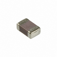
CAP 33000PF 50V CERAMIC X7R 0805
Manufacturer
Kemet
Series
C0805r
Datasheet
1.C0805C333K5RACTU.pdf
(9 pages)
Specifications of C0805C333K5RACTU
Capacitance
0.033µF
Voltage - Rated
50V
Tolerance
±10%
Temperature Coefficient
X7R
Mounting Type
Surface Mount, MLCC
Operating Temperature
-55°C ~ 125°C
Applications
General Purpose
Package / Case
0805 (2012 Metric)
Size / Dimension
0.079" L x 0.049" W (2.00mm x 1.25mm)
Thickness
0.78mm
Dielectric Characteristic
X7R
Capacitance Tolerance
± 10%
Voltage Rating
50VDC
Capacitor Case Style
0805
No. Of Pins
2
Capacitor Mounting
SMD
Rohs Compliant
Yes
Operating Temperature Range
- 55 C to + 125 C
Temperature Coefficient / Code
X7R
Product
General Type MLCCs
Dimensions
1.25 mm W x 2 mm L x 1.3 mm H
Lead Spacing
0.75 mm
Termination Style
SMD/SMT
Lead Free Status / RoHS Status
Lead free / RoHS Compliant
Features
-
Ratings
-
Lead Spacing
-
Lead Free Status / Rohs Status
Lead free / RoHS Compliant
Other names
399-1165-2
C0805C333K5RAC
C0805C333K5RAC7800
C0805C333K5RAC
C0805C333K5RAC7800
Available stocks
Company
Part Number
Manufacturer
Quantity
Price
Company:

Part Number:
C0805C333K5RACTU
Manufacturer:
KEMET
Quantity:
4 550


94
1. B1 dimension is a reference dimension for tape feeder clearance only.
2. The embossment hole location shall be measured from the sprocket hole controlling the location of the embossment. Dimensions of
3. Tape with components shall pass around radius “R” without damage (see sketch A). The minimum trailer length (Fig. 2) may require
4. The cavity defined by A
embossment location and hole location shall be applied independent of each other.
additional length to provide R min. for 12 mm embossed tape for reels with hub diameters approaching N min. (Table 2)
trude beyond the sealing plane of the cover tape, the chip can be removed from the cavity in a vertical direction without mechanical
restriction, rotation of the chip is limited to 20 degrees maximum in all 3 planes, and lateral movement of the chip is restricted to 0.5 mm
maximum in the pocket (not applicable to vertical clearance.)
The direction of the pull shall be opposite the direction of the carrier tape travel. The pull angle of the carrier
tape shall be 165 to 180 from the plane of the carrier tape. During peeling, the carrier and/or cover tape
shall be pulled at a velocity of 300 ±10 mm/minute.
reels (with C-7280). Note that 13” reels are preferred.
Refer to EIA-556.
12 mm
12 mm
8 mm
8 mm
and
©KEMET Electronics Corporation, P.O. Box 5928, Greenville, S.C. 29606, (864) 963-6300
Bar code labeling (standard or custom) shall be on the side of the reel opposite the sprocket holes.
Double
+0.004, -0.0)
(4 mm)
(8 mm)
Molded tantalum capacitors are available on either 180 mm (7") reels (standard) or 330 mm (13")
Single
+0.10 -0.0
12 mm
(0.059
8 mm
1.5
0
, B
0
, and K
(0.173)
(0.323)
ALUMINUM CHIP CAPACITORS
4.4
8.2
(0.069 ±0.004) (0.157 ±0.004) (0.079 ±0.002)
1.0 Kg Minimum.
TANTALUM, CERAMIC AND
1.75 ±0.10
0
The total peel strength of the cover tape from the carrier tape shall be:
shall be configured to surround the part with sufficient clearance such that the chip does not pro-
0.1 Newton to 1.0 Newton (10g to 100g)
0.1 Newton to 1.3 Newton (10g to 130g)
(0.039) (0.138 ±0.002)
(0.059) (0.217 ±0.002)
1.0
1.5
Packaging Information
4.0 ±0.10
3.5 ±0.05
5.5 ±0.05
Figure 1
(0.157 ±0.004) (0.984)
(0.315 ±0.004) (1.181)
2.0 ±0.05
4.0 ±0.10
8.0 ±0.10
(Metric will govern)
(0.024)
0.600
25.0
30.0
(0.098)
(0.181) (0.472 ±0.012)
(0.004)
0.100
2.5
4.6
(.315 ±0.012)
12.0 ±0.30
8.0 ±0.30
Related parts for C0805C333K5RACTU
Image
Part Number
Description
Manufacturer
Datasheet
Request
R

Part Number:
Description:
CAP, KEMET #F601BL105K250C
Manufacturer:
Kemet
Datasheet:
Part Number:
Description:
Manufacturer:
Kemet
Datasheet:
Part Number:
Description:
Manufacturer:
Kemet
Datasheet: