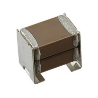
C1812C474MAR2C Kemet, C1812C474MAR2C Datasheet - Page 2

C1812C474MAR2C
Manufacturer Part Number
C1812C474MAR2C
Description
CAP CER KPS .47UF 250V X7R 1812
Manufacturer
Kemet
Series
KPSr
Datasheet
1.C1812C226M4R2C.pdf
(16 pages)
Specifications of C1812C474MAR2C
Capacitance
0.47µF
Voltage - Rated
250V
Tolerance
±20%
Temperature Coefficient
X7R
Mounting Type
Surface Mount, MLCC
Operating Temperature
-55°C ~ 125°C
Features
Stacked
Applications
General Purpose
Package / Case
1812 (4532 Metric)
Size / Dimension
0.197" L x 0.138" W (5.00mm x 3.50mm)
Thickness
5.00mm
Lead Free Status / RoHS Status
Lead free / RoHS Compliant
Ratings
-
Lead Spacing
-
Other names
399-5810-2
C1812C474MAR2CA
C1812C474MAR2CT500
C1812C474MAR2CA
C1812C474MAR2CT500
Surface Mount Multilayer Ceramic Chip Capacitors –KPS Series – Commercial Grade (X7R Dielectric)
Dimensions – Millimeters (Inches)
Outline Drawing
Qualification/Certification
Commercial grade products meet or exceed the performance and reliability standards outlined in Table 4 - Performance and Reliability
of this specification.
Environmental Compliance
RoHS PRC ( Peoples Republic of China) compliant
Electrical Parameters/Characteristics
To obtain IR limit, divide MΩ-µF value by the capacitance and compare to GΩ limit. Select the lower of the two limits.
Capacitance and Dissipation Factor (DF) measured under the following conditions:
© KEMET Electronics Corporation • P.O. Box 5928 • Greenville, SC 29606 (864) 963-6300 • www.kemet.com
Stack
Double
Capacitance Change with Reference to +25°C and 0 Vdc Applied (TCC):
Single
Chip
Ref
1kHz ± 50Hz and 1.0 ± 0.2 Vrms if capacitance ≤10µF
120Hz ± 10Hz and 0.5 ± 0.1 Vrms if capacitance >10µF
C
D
G
A
B
E
F
Code
Size
1210
2220
1210
2220
EIA
1812
1812
Dissipation Factor (DF) Maximum Limits @ 25ºC:
Metric
Leadframe Attach
Code
Aging Rate (Max % Cap Loss/Decade Hour):
Size
3225
4532
5650
3225
4532
5650
Termination
Leadframe
Electrode
Name
Dielectric
Insulation Resistance (IR) Limit @ 25°C:
6.00 (.236) ± 0.50 (.020) 5.00 (.197) ± 0.50 (.020) 3.50 (.138) ± 0.30 (.012) 1.60 (.063) ± 0.30 (.012)
6.00 (.236) ± 0.50 (.020) 5.00 (.197) ± 0.50 (.020) 5.00 (.197) ± 0.50 (.020) 1.60 (.063) ± 0.30 (.012)
3.50 (.138) ± 0.30 (.012) 2.60 (.102) ± 0.30 (.012) 3.35 (.132) ± 0.10 (.004) 0.80 (.032) ± 0.15 (.006)
5.00 (.197) ± 0.50 (.020) 3.50 (.138) ± 0.50 (.020) 2.65 (.104) ± 0.35 (.014) 1.10 (.043) ± 0.30 (.012)
3.50 (.138) ± 0.30 (.012) 2.60 (.102) ± 0.30 (.012) 6.15 (.242) ± 0.15 (.006) 0.80 (.031) ± 0.15 (.006)
5.00 (.197) ± 0.50 (.020) 3.50 (.138) ± 0.50 (.020) 5.00 (.197) ± 0.50 (.020) 1.10 (.043) ± 0.30 (.012)
Dielectric Withstanding Voltage:
Operating Temperature Range:
L Length
Phosphor Bronze - Alloy 510
High Temp Solder
Material
BaTiO
Cu
Sn
Ni
Ni
3
W Width
-55°C to +125°C
±15%
3.5%
250% of rated voltage
(5 ± 1 seconds and charge/discharge not exceeding 50mA)
5% (10V), 3.5% (16V & 25V) and 2.5% (50V to 200V)
See Insulation Resistance Limit Table page 3
Single or Double
Chip Stack
Top View
T Thickness
Double Chip Stack
LW Lead Width
Profile View
C1020-4 • 6/22/2010
Single Chip Stack
Solder Reflow
Technique
Mounting
2 2


