ECJ-2VB1E823K Panasonic - ECG, ECJ-2VB1E823K Datasheet - Page 4
ECJ-2VB1E823K
Manufacturer Part Number
ECJ-2VB1E823K
Description
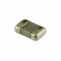
CAP .082UF 25V CERAMIC X7R 0805
Manufacturer
Panasonic - ECG
Series
ECJr
Datasheets
1.ECJ-RVB1H332M.pdf
(6 pages)
2.ECJ-RVB1H332M.pdf
(2 pages)
3.ECJ-RVB1H332M.pdf
(1 pages)
4.ECJ-RVB1H332M.pdf
(3 pages)
5.ECJ-0EB1H102K.pdf
(12 pages)
Specifications of ECJ-2VB1E823K
Capacitance
0.082µF
Voltage - Rated
25V
Tolerance
±10%
Temperature Coefficient
X7R
Mounting Type
Surface Mount, MLCC
Operating Temperature
-55°C ~ 125°C
Features
Low ESR
Applications
General Purpose
Package / Case
0805 (2012 Metric)
Size / Dimension
0.079" L x 0.049" W (2.00mm x 1.25mm)
Thickness
0.85mm
Lead Free Status / RoHS Status
Lead free / RoHS Compliant
Ratings
-
Lead Spacing
-
Other names
ECJ2VB1E823K
PCC1827TR
PCC1827TR


3. Chip Mounting Consideration
4. Selection of Soldering Flux
Design and specifi cations are each subject to change without notice. Ask factory for the current technical specifi cations before purchase and/or use.
Should a safety concern arise regarding this product, please be sure to contact us immediately.
Single surface
mouting
Double surface
mounting
(5) Insuffi cient curing may cause the Capacitor to fall
(1) When mounting the Capacitors/components on a
(2) Maintenance and inspection of the Chip Mounter
(3) If the bottom dead center of the vacuum nozzle
(4) The closing dimensions of the positioning chucks
(5) Maximum stroke of the nozzle shall be adjusted
Soldering fl ux may seriously affect the performance of the
Capacitors. The following shall be confi rmed before use.
(1) The soldering fl ux should have a halogen based
(2) When applying water-soluble soldering fl ux, wash
off after or during soldering. In addition, insulation
resistance between terminal electrodes may deteriorate
due to moisture absorption. In order to prevent these
problems, please observe proper curing conditions.
PC board, the Capacitor bodies shall be free from
excessive impact loads such as mechanical impact
or stress due to the positioning, pushing force and
displacement of vacuum nozzles during mounting.
must be performed regularly.
is too low, the Capacitor will crack from excessive
force during mounting.
The following precautions and recommendations are
for your reference.
(a) Set and adjust the bottom dead center of the
(b) Set the pushing force of the vacuum nozzle
(c) For double surface mounting, apply a supporting
(d) Adjust the vacuum nozzles so that their bottom
shall be controlled. Maintenance and replacement
of positioning chucks shall be performed regularly
to prevent chipping or cracking of the Capacitors
caused by mechanical impact during positioning
due to worn positioning chucks.
so that the maximum bending of PC board does
not exceed 0.5 mm at 90 mm span. The PC board
shall be supported by an adequate number of
supporting pins.
content of 0.1 wt. % (converted to chlorine) or below.
Do not use soldering fl ux with strong acid.
the Capacitors suffi ciently because the soldering fl ux
residue on the surface of PC boards may deteriorate
the insulation resistance on the Capacitors surface.
Item
vacuum nozzles to the upper surface of the PC
board after correcting the warp of the PC board.
during mounting to 1 to 3 N in static load.
pin on the rear surface of the PC board to suppress
the bending of the PC board in order to minimize
the impact of the vacuum nozzles. Typical examples
are shown in the table below.
dead center during mounting is not too low.
Prohibited mounting
Separation of Solder
Crack
Crack
Supporting pin
The supporting pin does not necessarily
have to be positioned beneath the Capacitor.
Supporting pin
Recommended
mounting
– EC51 –
5. Soldering
For products specifi ed in individual specifi cations, avoid
fl ow soldering.
1 Preheating
2 Temp. rise
3 Heating
4 Peak
5 Gradual cooling Peak temp. to 140 °C
5.1 Flow Soldering
5.2 Refl ow Soldering
For fl ow soldering, abnormal and large thermal and
mechanical stress, caused by the “Temperature Gradient”
between the mounted Capacitors and melted solder in a
soldering bath may be applied directly to the Capacitors,
resulting in failure and damage of the Capacitors.
Therefore it is essential that soldering process follow
these recommended conditions.
(1) Application of Soldering fl ux:
(2) Preheating:
(3) Immersion into Soldering Bath:
(4) Gradual Cooling:
(5) Flux Cleaning:
(6) Performing fl ow soldering once under the conditions
The refl ow soldering temperature conditions are each
temperature curves of Preheating, Temp. rise, Heating,
Peak and Gradual cooling. Large temperature difference
caused by rapid heat application to the Capacitors may
lead to excessive thermal stresses, contributing to the
thermal cracks. The Preheating temperature requires
controlling with great care so that tombstone phenomenon
may be prevented.
0603 to 1206, 0508, 0612
Recommended profi le for Flow soldering [Ex.]
The soldering fl ux shall be applied to the mounted
Capacitors thinly and uniformly by foaming method.
The mounted Capacitors/ Components shall be
pre-heated suffi ciently so that the “Temperature
Gradient” between the Capacitors/Components
and the melted solder shall be 150 °C max. (100
to 130 °C)
The Capacitors shall be immersed into a soldering
bath of 240 to 260 °C for 3 to 5 seconds.
The Capacitors shall be cooled gradually to room
ambient temperature at cooling temperature rates of
8 °C/s max. from 250 °C to 170 °C and 4 °C/s max.
from 170 °C to 130 °C.
When the Capacitors are immersed into a cleaning
solvent, be sure that the surface temperatures of
the devices do not exceed 100 °C.
shown in the fi gure below [Recommended profi le of
Flow soldering (Ex)] will not cause any problems.
However, pay attention to the possible warp and
bending of the PC board.
260
240
Item
0
<Allowable temperature difference
60 to 120 s
Size
Multilayer Ceramic Capacitors
Preheating temp to
140 to 180 °C
Temperature
260 °C max.
220 °C min.
Peak temp.
Soldering Gradual cooling
3 to 5 s
(at ordinary temperature)
Period or Speed
Temp. Tol
60 to 120 sec
T < 150 °C
2 to 5 °C/sec
1 to 4 °C/sec
60 sec max.
10 sec max.
00 Sep. 2008
T>
Time
Related parts for ECJ-2VB1E823K
Image
Part Number
Description
Manufacturer
Datasheet
Request
R

Part Number:
Description:
CAP ARRAY 22PF 50V NP0 0504
Manufacturer:
Panasonic - ECG
Datasheet:
Part Number:
Description:
CAP ARRAY 10PF 50V NP0 0504
Manufacturer:
Panasonic - ECG
Datasheet:
Part Number:
Description:
CAP ARRAY 100PF 50V NP0 0504
Manufacturer:
Panasonic - ECG
Datasheet:
Part Number:
Description:
CAP ARRAY 47PF 50V NP0 0504
Manufacturer:
Panasonic - ECG
Datasheet:
Part Number:
Description:
CAP ARRAY 2.2UF 6.3V X5R 0504
Manufacturer:
Panasonic - ECG
Datasheet:
Part Number:
Description:
CAP ARRAY .1UF 10V X5R 0504
Manufacturer:
Panasonic - ECG
Datasheet:
Part Number:
Description:
CAP ARRAY 1UF 6.3V X5R 0504
Manufacturer:
Panasonic - ECG
Datasheet:
Part Number:
Description:
CAP ARRAY 1UF 6.3V X5R 0504
Manufacturer:
Panasonic - ECG
Datasheet:
Part Number:
Description:
CAP ARRAY 1UF 10V X5R 0504
Manufacturer:
Panasonic - ECG
Datasheet:
Part Number:
Description:
CAP ARRAY 1UF 10V X5R 0504
Manufacturer:
Panasonic - ECG
Datasheet:


Part Number:
Description:
MICROPHONE OMNI 6X2.2MM W/CAP
Manufacturer:
Panasonic - ECG
Datasheet:

Part Number:
Description:
CAP .01UF 100V PEN FILM 1210 5%
Manufacturer:
Panasonic - ECG
Datasheet:

Part Number:
Description:
FILTER LINE 23.3MH 2A
Manufacturer:
Panasonic - ECG
Datasheet:

Part Number:
Description:
SAW FILTER PCS 1960 MHZ 50/150
Manufacturer:
Panasonic - ECG
Datasheet: