C2012Y5V0J106Z/10 TDK Corporation, C2012Y5V0J106Z/10 Datasheet - Page 55
C2012Y5V0J106Z/10
Manufacturer Part Number
C2012Y5V0J106Z/10
Description
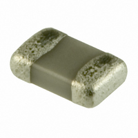
CAP CER 10UF 6.3V Y5V 0805 T/R
Manufacturer
TDK Corporation
Series
Cr
Specifications of C2012Y5V0J106Z/10
Capacitance
10µF
Voltage - Rated
6.3V
Tolerance
-20%, +80%
Temperature Coefficient
Y5V (F)
Mounting Type
Surface Mount, MLCC
Operating Temperature
-30°C ~ 85°C
Features
Low ESR
Applications
General Purpose
Package / Case
0805 (2012 Metric)
Size / Dimension
0.079" L x 0.049" W (2.00mm x 1.25mm)
Thickness
1.25mm
Lead Free Status / RoHS Status
Lead free / RoHS Compliant
Ratings
-
Lead Spacing
-
Other names
C2012Y5V0J106ZT/10
C2012Y5V0J106ZT10
C2012Y5V0J106ZT10
C2012Y5V0J106ZT10
C2012Y5V0J106ZT10


• All specifications are subject to change without notice. Please read the precautions before using the product.
No.
13
14
General
Specifications
Item
Vibration
External
appearance
Capacitance
Q (Class 1)
D.F. (Class 2)
Temperature cycle
External
appearance
Capacitance
Q (Class 1)
D.F. (Class 2)
Insulation
Resistance
Voltage
Proof
Performance
No mechanical damage.
Meet the initial spec.
No mechanical damage.
Meet the initial spec.
Meet the initial spec.
No insulation breakdown or other
damage.
Characteristics
Class 1
Class 2
Rated
Capacitance
C ≥ 30pF
C < 30pF
Characteristics
Class 1
Class 2
Rated
Capacitance
C ≥ 30pF
C < 30pF
C0G
C : Rated capacitance (pF)
C0G
C : Rated capacitance (pF)
X5R
X7R
Y5V
X5R
X7R
Y5V
Change from the
value before test
±2.5% or ±0.25pF,
whichever larger.
± 7.5 %
± 7.5 %
± 20 %
Q
1,000 min.
400+20×C min.
Change from the
value before test
±2.5% or ±0.25pF,
whichever larger.
± 15 %
± 15 %
± 20 %
Q
1,000 min.
400+20×C min.
C Series — General Application
Test or Inspection Method
Reflow solder the capacitor on P.C. board (shown in
Appendix 1a or Appendix 1b) before testing.
Vibrate the capacitor with amplitude of 1.5mm P-P
changing the frequencies from 10Hz to 55Hz and back
to 10Hz after 1min. Repeat this for 2h each in 3
perpendicular directions.
Reflow solder the capacitor on P.C. board (shown in
Appendix 1a or Appendix 1b) before testing.
Expose the capacitor in the condition step1 through
step 4 and repeat 5 times consecutively.
Leave the capacitor in ambient conditions for 6 to 24h
(Class 1) or 24±2h (Class 2) before measurement.
Step
1
2
3
4
US Catalog // C Series — General Application // Version A11
Temperature (ºC)
Min. operating temp. ±3
Reference Temp.
Max. operating temp. ± 2
Reference Temp.
Time (min.)
30 ± 3
2 — 5
30 ± 2
2 - 5
Related parts for C2012Y5V0J106Z/10
Image
Part Number
Description
Manufacturer
Datasheet
Request
R

Part Number:
Description:
TDK DC to DC Converters, DC to AC Inverters
Manufacturer:
TDK Corporation
Datasheet:
Part Number:
Description:
TDK DC to DC Converters, DC to AC Inverters
Manufacturer:
TDK Corporation
Datasheet: