LLL31MR71A155MA01L Murata Electronics North America, LLL31MR71A155MA01L Datasheet - Page 191
LLL31MR71A155MA01L
Manufacturer Part Number
LLL31MR71A155MA01L
Description
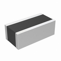
CAP CER 1.5UF 10V X7R 0612
Manufacturer
Murata Electronics North America
Series
LLLr
Datasheets
1.GNM1M2R71E472MA01D.pdf
(4 pages)
2.GNM1M2R61A105ME14D.pdf
(221 pages)
3.LLL185R70J224MA01L.pdf
(4 pages)
Specifications of LLL31MR71A155MA01L
Capacitance
1.5µF
Voltage - Rated
10V
Tolerance
±20%
Temperature Coefficient
X7R
Mounting Type
Surface Mount, MLCC
Operating Temperature
-55°C ~ 125°C
Features
Low ESL
Applications
General Purpose
Package / Case
1206 (3216 Metric) Wide, 0612 (1632 Metric)
Size / Dimension
0.063" L x 0.126" W (1.60mm x 3.20mm)
Thickness
1.15mm
Lead Free Status / RoHS Status
Lead free / RoHS Compliant
Ratings
-
Lead Spacing
-
Other names
490-4390-2


!Note
• This PDF catalog is downloaded from the website of Murata Manufacturing co., ltd. Therefore, it’s specifications are subject to change or our products in it may be discontinued without advance notice. Please check with our
• This PDF catalog has only typical specifications because there is no space for detailed specifications. Therefore, please approve our product specifications or transact the approval sheet for product specifications before ordering.
sales representatives or product engineers before ordering.
!Note
190
No.
17
18 Life
19
* "Room condition" Temperature: 15 to 35D, Relative humidity: 45 to 75%, Atmospheric pressure: 86 to 106kPa
AC250V(r.m.s.) Type (Which Meet Japanese Law) Specifications and Test Methods
GA2 Series Specifications and Test Methods
Continued from the preceding page.
Humidity
(Steady
Humidity
Loading
State)
• Please read rating and !CAUTION (for storage, operating, rating, soldering, mounting and handling) in this catalog to prevent smoking and/or burning, etc.
• This catalog has only typical specifications because there is no space for detailed specifications. Therefore, please approve our product specifications or transact the approval sheet for product specifications before ordering.
Item
Appearance
Capacitance
Change
D.F.
I.R.
Dielectric
Strength
Appearance
Capacitance
Change
D.F.
I.R.
Dielectric
Strength
Appearance
Capacitance
Change
D.F.
I.R.
Dielectric
Strength
No marking defects
Within T15%
0.05 max.
More than 1,000M
In accordance with item No.4
No marking defects
Within T20%
0.05 max.
More than 1,000M
In accordance with item No.4
No marking defects
Within T15%
0.05 max.
More than 1,000M
In accordance with item No.4
Specifications
Let the capacitor sit at 40T2D and relative humidity of 90 to 95%
for 500
Remove and let sit for 24T2 hrs. at room condition,* then
measure.
#Pretreatment
Apply voltage and time as in Table at maximum operating
temperature T3D. Remove and let sit for 24T2 hrs. at room
condition,* then measure. The charge / discharge current is
less than 50mA.
* Except that once each hour the voltage is increased to
Apply the rated voltage at 40T2D and relative humidity of 90 to
95% for 500
Remove and let sit for 24T2 hrs. at room condition,* then
measure.
#Pretreatment
Perform a heat treatment at 150
let sit for 24T2 hrs. at room condition.*
#Pretreatment
Apply test voltage for 60T5 min. at test temperature.
Remove and let sit for 24T2 hrs. at room condition.*
Apply test voltage for 60T5 min. at test temperature.
Remove and let sit for 24T2 hrs. at room condition.*
AC1,000V (r.m.s.) for 0.1 sec.
Nominal Capacitance
W24
Y
CU10,000pF
CF10,000pF
0
hrs.
W24
Y
0
hrs.
Test Method
1,000
1,500
Test Time
W
Y10
W48
Y
W48
Y
0
D for 60T5 min. and then
0
0
hrs.
hrs.
AC300V (r.m.s.)
AC500V (r.m.s.) *
Test Voltage
C02E.pdf
10.12.20
Related parts for LLL31MR71A155MA01L
Image
Part Number
Description
Manufacturer
Datasheet
Request
R

Part Number:
Description:
BUZZER PIEZO 25VP-P SMD
Manufacturer:
Murata Electronics North America

Part Number:
Description:
CAP 4-ARRAY 680PF 100V X7R 1206
Manufacturer:
Murata Electronics North America
Datasheet:
Part Number:
Description:
CAP 4-ARRAY 1000PF 100V X7R 1206
Manufacturer:
Murata Electronics North America
Datasheet:
Part Number:
Description:
CAP 4-ARRAY 1800PF 100V X7R 1206
Manufacturer:
Murata Electronics North America
Datasheet:
Part Number:
Description:
CAP 4-ARRAY 68000PF 16V X7R 1206
Manufacturer:
Murata Electronics North America
Datasheet:

Part Number:
Description:
CAP CER 1000PF 50V 10% X7R 0402
Manufacturer:
Murata Electronics North America
Datasheet:
Part Number:
Description:
CAP CER 10000PF 16V 10% X7R 0402
Manufacturer:
Murata Electronics North America
Datasheet:

Part Number:
Description:
CAP 5.5-25PF 2.5X3.2MM SMD
Manufacturer:
Murata Electronics North America
Datasheet:

Part Number:
Description:
CAP 4.5-20PF 2.5X3.2MM SMD
Manufacturer:
Murata Electronics North America
Datasheet:

Part Number:
Description:
CAP 5.0-20PF 3.2X4.5MM SMD RED
Manufacturer:
Murata Electronics North America
Datasheet:

Part Number:
Description:
CAP 2.0-6.0PF 3.2X4.5MM SMD BLU
Manufacturer:
Murata Electronics North America
Datasheet:

Part Number:
Description:
CAP 1.4-3.0PF 3.2X4.5MM SMD BRN
Manufacturer:
Murata Electronics North America
Datasheet:

Part Number:
Description:
CAP 3.0-10PF 3.2X4.5MM SMD WHT
Manufacturer:
Murata Electronics North America
Datasheet:

Part Number:
Description:
CAP 2.0-6.0PF 4X4.5MM TOPADJ BLU
Manufacturer:
Murata Electronics North America
Datasheet:

Part Number:
Description:
CAP 8.5-40PF 4X4.5MM TOPADJ YEL
Manufacturer:
Murata Electronics North America
Datasheet: