FK26X7R2E223K TDK Corporation, FK26X7R2E223K Datasheet - Page 2
FK26X7R2E223K
Manufacturer Part Number
FK26X7R2E223K
Description
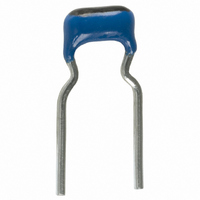
CAP CER 22000PF 250V X7R 10% RAD
Manufacturer
TDK Corporation
Series
FKr
Datasheet
1.FK28C0G2A101J.pdf
(8 pages)
Specifications of FK26X7R2E223K
Capacitance
0.022µF
Voltage - Rated
250V
Tolerance
±10%
Temperature Coefficient
X7R
Mounting Type
Through Hole
Operating Temperature
-55°C ~ 125°C
Applications
General Purpose
Package / Case
Radial
Size / Dimension
0.236" L x 0.217" W (6.00mm x 5.50mm)
Thickness
3.50mm Max
Lead Spacing
0.197" (5.00mm)
Lead Style
Kinked
Lead Free Status / RoHS Status
Lead free / RoHS Compliant
Features
-
Ratings
-
Other names
445-2635


Dipped Radial Ceramic Capacitors
Mid Voltage FK Series
FEATURES
• Due to the technological progress in creating thinner layers of
• It maintains a high level of reliability under specified environ-
• Its residual inductance is small and it provides good frequency
• The leads are formed with a "kink" to achieve consistent
• Also available are products that meet taping specifications for
PRODUCT IDENTIFICATION
FK 28 C0G 1H 101 J
(1) (2) (3) (4) (5) (6)
(1) Series name
(2) Dimensions and shapes of lead wire
Type
28
24
26
20
22
18
14
(3) Capacitance temperature characteristics
Class 1 (Temperature compensation)
Temperature
characteristics
C0G
Class 2 (Temperature stable and general purpose)
Temperature
characteristics
X7R
• Conformity to RoHS Directive: This means that, in conformity with EU Directive 2002/95/EC, lead, cadmium, mercury, hexavalent chromium, and specific
• All specifications are subject to change without notice.
bromine-based flame retardants, PBB and PBDE, have not been used, except for exempted applications.
ceramic dielectric and achieving multilayer lamination, this
product provides large electrostatic capacity.
mental conditions.
characteristics.
insertion heights and facilitate the release of gases during
soldering for dramatically improved solderability.
automatic insertions, which contribute to reducing on-board
costs.
Fig.1
L max. W max. T max. F
4.0
4.5
5.5
5.5
7.5
4.0
4.5
L
F
5.5
5.5
6.0
7.0
8.0
5.5
5.5
ød
Capacitance change
0±30ppm/°C
Capacitance change
±15%
2.5
2.5
3.5
4.0
4.0
2.5
2.5
Fig.2
L
F
(7)
ød
5.0±1.0
5.0±1.0
5.0±1.0
5.0±1.0
5.0±1.0
2.5±0.8
2.5±0.8
T
7±2
7±2
7±2
7±2
7±2
5+3,–1
5+3,–1
Temperature range
–55 to +125°C
Temperature range
–55 to +125°C
0.5+0.1,–0.03 2
0.5+0.1,–0.03 2
ød
0.5+0.1,–0.03 1
0.5+0.1,–0.03 1
0.5+0.1,–0.03 1
0.5+0.1,–0.03 1
0.5+0.1,–0.03 1
Dimensions in mm
Fig
(4) Rated voltage Edc
2A
2E
2J
(5) Nominal capacitance
The capacitance is expressed in three digit codes and in units of
pico farads (pF).
The first and second digits identify the first and second significant
figures of the capacitance.
The third digit identifies the multiplier.
102
333
474
(6) Capacitance tolerance
Symbol
J
K
M
(7) TDK internal code
100V
250V
630V
1,000pF
33,000pF
470,000pF
Tolerance
±5%
±10%
±20%
Conformity to RoHS Directive
001-04 / 20060618 / e4942_fk.fm
(1/7)
Related parts for FK26X7R2E223K
Image
Part Number
Description
Manufacturer
Datasheet
Request
R

Part Number:
Description:
TDK DC to DC Converters, DC to AC Inverters
Manufacturer:
TDK Corporation
Datasheet:
Part Number:
Description:
TDK DC to DC Converters, DC to AC Inverters
Manufacturer:
TDK Corporation
Datasheet: