VJ1210A270KBCAT4X Vishay, VJ1210A270KBCAT4X Datasheet - Page 14
VJ1210A270KBCAT4X
Manufacturer Part Number
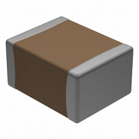
VJ1210A270KBCAT4X
Description
CAP CER 27PF 10% 200V NP0 1210
Manufacturer
Vishay
Series
VJr
Datasheet
1.VJ1808A681JXCAT.pdf
(16 pages)
Specifications of VJ1210A270KBCAT4X
Capacitance
27pF
Voltage - Rated
200V
Tolerance
±10%
Temperature Coefficient
C0G, NP0
Mounting Type
Surface Mount, MLCC
Operating Temperature
-55°C ~ 125°C
Features
Soft Termination
Applications
Boardflex Sensitive
Package / Case
1210 (3225 Metric)
Size / Dimension
0.126" L x 0.098" W (3.20mm x 2.50mm)
Thickness
1.70mm Max
Lead Free Status / RoHS Status
Lead free / RoHS Compliant
Ratings
-
Lead Spacing
-


BOARDFLEX SENSITIVE APPLICATIONS - SOLUTION:
A predominant failure mode in multilayer ceramic chip capacitors is cracking caused by board flexure. Cracks can then create
a path for current to pass from one electrode through the dielectric to an opposing electrode or from the terminations at one
end of the MLCC through the dielectric to an opposing electrode. This may subsequently result in capacitance loss, leakage -
low Insulation Resistance (IR) - and/or more seriously, high current shorts. A short circuit condition in the surface mounted
capacitors can cause further failures of downstream components. Vishay’s Open Mode Design Capacitors (VJ OMD - Cap.
series) reduce the risk of these destructive conditions through MLCC designs that prevent board flexure cracks reaching the
opposing electrode.
VJ OMD - Cap. MLCCs reduce the risk of early field failures associated with board flex cracks. However, it is important to note
that even in the open mode designs the presence of flexure related cracks can cause capacitance loss leading to localized
stresses on the parts. eventually, depending on the application environment, including such factors and high voltage pulse
frequency and thermal cycling this may lead to internal breakdown of the component.
POLYMER TERMINATION
Polymer termination provides additional protection against board flexure damage by absorbing greater mechanical and thermal
stresses. Components can be packaged, transported, stored and handled the same standard terminated product. Wave and
reflow soldering of MLCC does not require modification to equipment and/or process. Polymer termination greatly reduces the
risk of mechanical cracking however it does not completely eliminate.
Document Number: 45198
Revision: 25-Jan-11
STANDARD TERMINATION
Exposed Electrodes = Electrical short
Surface Mount Multilayer Ceramic Chip Capacitor
Solutions for Boardflex Sensitive Applications
100 %
80 %
70 %
60 %
50 %
40 %
30 %
20 %
10 %
90 %
0 %
0.0
For technical questions, contact:
TYPICAL BEND TEST RESULTS 2220 CASE SIZE
1.0
Standard Termination
Polymer Termination
Log. (Standard Termination)
Log. (Polymer Termination)
2.0
BOARD FLEXURE in (mm)
3.0
4.0
5.0
OMD CAP PLUS POLYMER TERMINATION
No Exposed Electrodes = No Electrical short
mlcc@vishay.com
6.0
7.0
8.0
9.0
VJ OMD Series
Vishay Vitramon
www.vishay.com
121
Related parts for VJ1210A270KBCAT4X
Image
Part Number
Description
Manufacturer
Datasheet
Request
R

Part Number:
Description:
357-036-542-201 CARDEDGE 36POS DL .156 BLK LOPRO
Manufacturer:
Vishay
Datasheet:
Part Number:
Description:
357-036-542-201 CARDEDGE 36POS DL .156 BLK LOPRO
Manufacturer:
Vishay
Datasheet:
Part Number:
Description:
357-036-542-201 CARDEDGE 36POS DL .156 BLK LOPRO
Manufacturer:
Vishay
Datasheet:
Part Number:
Description:
357-036-542-201 CARDEDGE 36POS DL .156 BLK LOPRO
Manufacturer:
Vishay
Datasheet:
Part Number:
Description:
357-036-542-201 CARDEDGE 36POS DL .156 BLK LOPRO
Manufacturer:
Vishay
Datasheet:
Part Number:
Description:
357-036-542-201 CARDEDGE 36POS DL .156 BLK LOPRO
Manufacturer:
Vishay
Datasheet:
Part Number:
Description:
357-036-542-201 CARDEDGE 36POS DL .156 BLK LOPRO
Manufacturer:
Vishay
Datasheet:
Part Number:
Description:
357-036-542-201 CARDEDGE 36POS DL .156 BLK LOPRO
Manufacturer:
Vishay
Datasheet:
Part Number:
Description:
357-036-542-201 CARDEDGE 36POS DL .156 BLK LOPRO
Manufacturer:
Vishay
Datasheet:
Part Number:
Description:
357-036-542-201 CARDEDGE 36POS DL .156 BLK LOPRO
Manufacturer:
Vishay
Datasheet:
Part Number:
Description:
357-036-542-201 CARDEDGE 36POS DL .156 BLK LOPRO
Manufacturer:
Vishay
Datasheet:
Part Number:
Description:
357-036-542-201 CARDEDGE 36POS DL .156 BLK LOPRO
Manufacturer:
Vishay
Datasheet:
Part Number:
Description:
357-036-542-201 CARDEDGE 36POS DL .156 BLK LOPRO
Manufacturer:
Vishay
Datasheet:
Part Number:
Description:
357-036-542-201 CARDEDGE 36POS DL .156 BLK LOPRO
Manufacturer:
Vishay
Datasheet:
Part Number:
Description:
357-036-542-201 CARDEDGE 36POS DL .156 BLK LOPRO
Manufacturer:
Vishay
Datasheet: